Kevin Wen's Blog


  • 首页

  • 归档

  • 标签

How escher support physically based render

发表于 2019-03-23 | 阅读次数

0x1 物理渲染和光栅化渲染

0x21 传统光栅化渲染器的特点

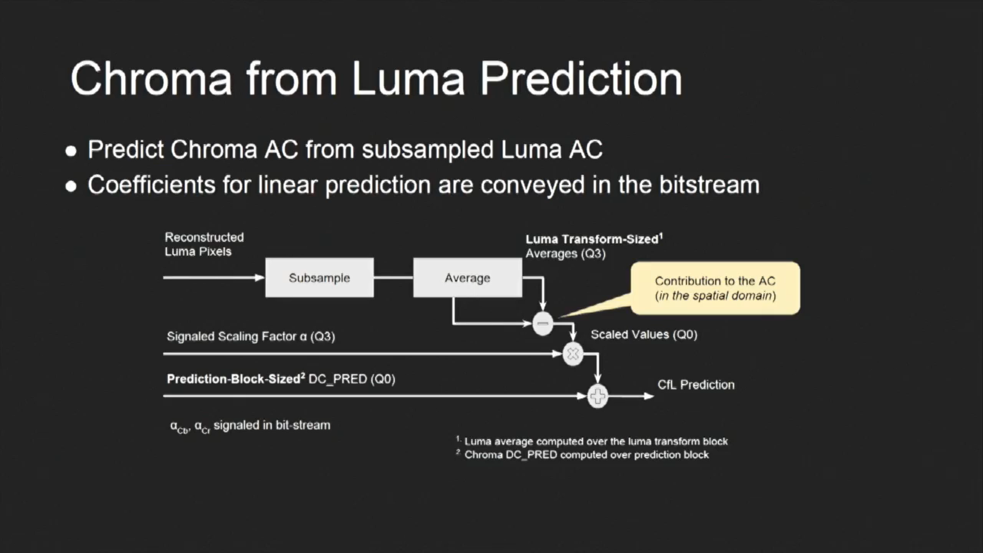
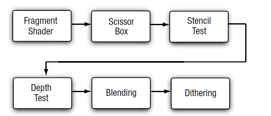
光栅化是指把3D空间的几何图形及其色彩信息转换至2D计算机屏幕上像素的过程。光栅化渲染器的pipeline包括Vertex Shader,Rasterization,Fragment Shader等阶段,目前GPU硬件也是采用这种高效率的光栅化架构。基于这些GPU硬件设计的渲染API有Windows上的DirectX,跨平台的OpenGL和Vulkan,已经Apple的Metal等。应用程序可以基于这些渲染API开发出酷炫的3D效果。但是这种光栅化的缺点也很明显,那就是无法完全模拟真实场景下的光线传播,导致绘制效果失真。
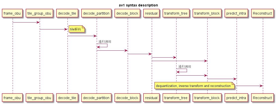
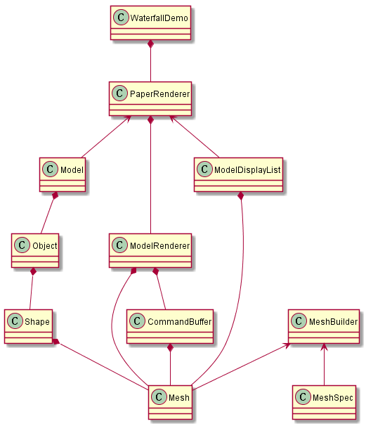
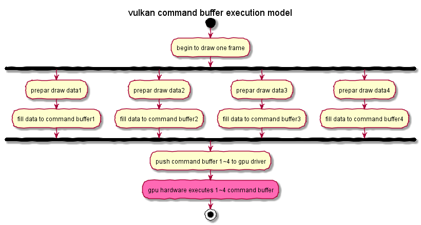
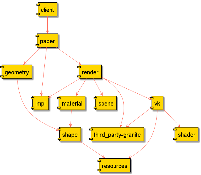
下图说明了光栅化渲染器的流水线。

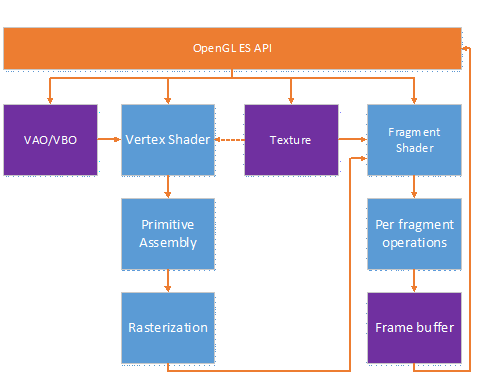
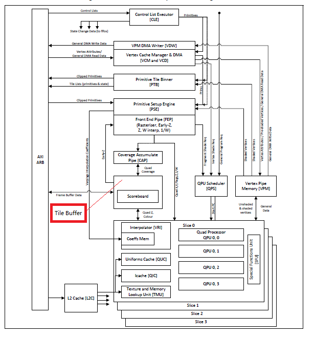
现代GPU中vertex shader和fragment shader一般是逻辑的概念,当时比较早的GPU是采用两种独立的硬件单元(不是Unified Shader)来实现的,如ARM Mali-400就是这种架构,这种架构的缺点是vertex shader和fragment shader的负载没办法平衡,极端情况下会出现其中一种硬件Shader满负荷运行,另外一种硬件Shader空闲的情况。后来的架构一般是基于通用可编程计算单元实现这些功能。也就是我们常说的Unified Shader架构。如树莓派中的Soc VideoCore采用了BroadCom V3D GPU, 其中的Unified Shader中采用QPU这种通用可编程计算单元来实现。

移动GPU相对桌面GPU的架构也有差别,因为移动平台上对带宽及功耗的要求都比较高。
桌面GPU一般采用IMR(Immediate Mode Rendering)架构, 这种架构需要同时对该次渲染的全部物体进行处理,需要频繁访问系统帧缓存(位于系统内存里),故对带宽要求较高。

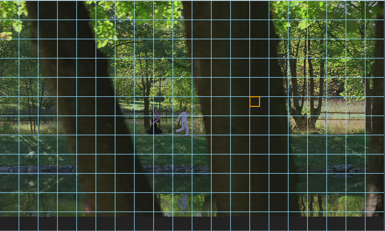
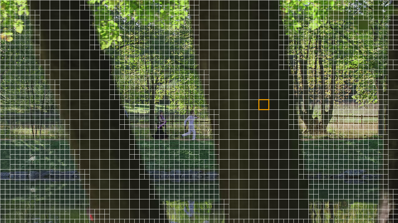
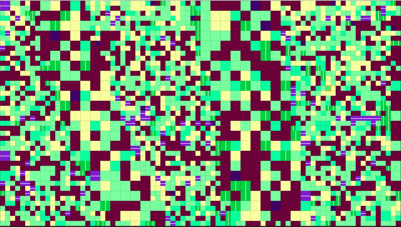
移动GPU一般采用TBR架构(Tile Based Rendering)。TBR架构包括两个阶段Tiling和Binning。Tiling阶段把整个画面分成小块,然后计算每个小块中有哪些三角形需要处理。Binning阶段每次只对一个小块中包括的三角形进行处理,这种方式避免了对帧缓存(位于系统内存里)的频繁读写和修改,因为这些小块中的三角形的渲染是在GPU上的高速缓存里进行,所以能节约带宽,同时也减少了功耗。

Imagination在TBR架构的基础上又提出了TBDR(Tile Based Deferred Rendering), 在执行shading之前加入HSR(Hidded Surface Remove), 这个模块利用vertex shader/rasterization之后的fragment的深度值来优化掉不必要的计算。

0x22 物理渲染器的特点

物理渲染器PBR(Physically Based Rendering),也称光线跟踪器(Ray tracer)。采用该算法渲染的结果看起来更真实,因为它基于物理参数的方法来编写材质,而且考虑了光线的发射和折射,材质对光线的吸收等。

光线跟踪算法描述如下,沿着到达视点的光线的反方向跟踪,经过屏幕上每一个象素,找出与视线相交的物体表面点,并继续跟踪,找出影响点光强的所有光源,从而算出点上精确的光线强度。这种算法计算量极大,一般用于离线渲染。

一个典型的物理渲染器包括如下模块。
相机
光线-对象相交测试
光照分布/光线传播
递归光线跟踪机制

考虑到PBR的计算量太大,只适合离线渲染,后来基于全局光照Global Illuslaton技术的来实现实时PBR,因为考虑到了速度的提升,在渲染质量上会有损失。

早期Ray tracing的硬件有德国萨尔兰大学计算机图形小组在2005年的SIGGRAPH上展示了第一个实时光线追踪加速硬件——RPU(Ray Processing Unit),最近有NVIDIA在GPU硬件中加入了Ray tracing。

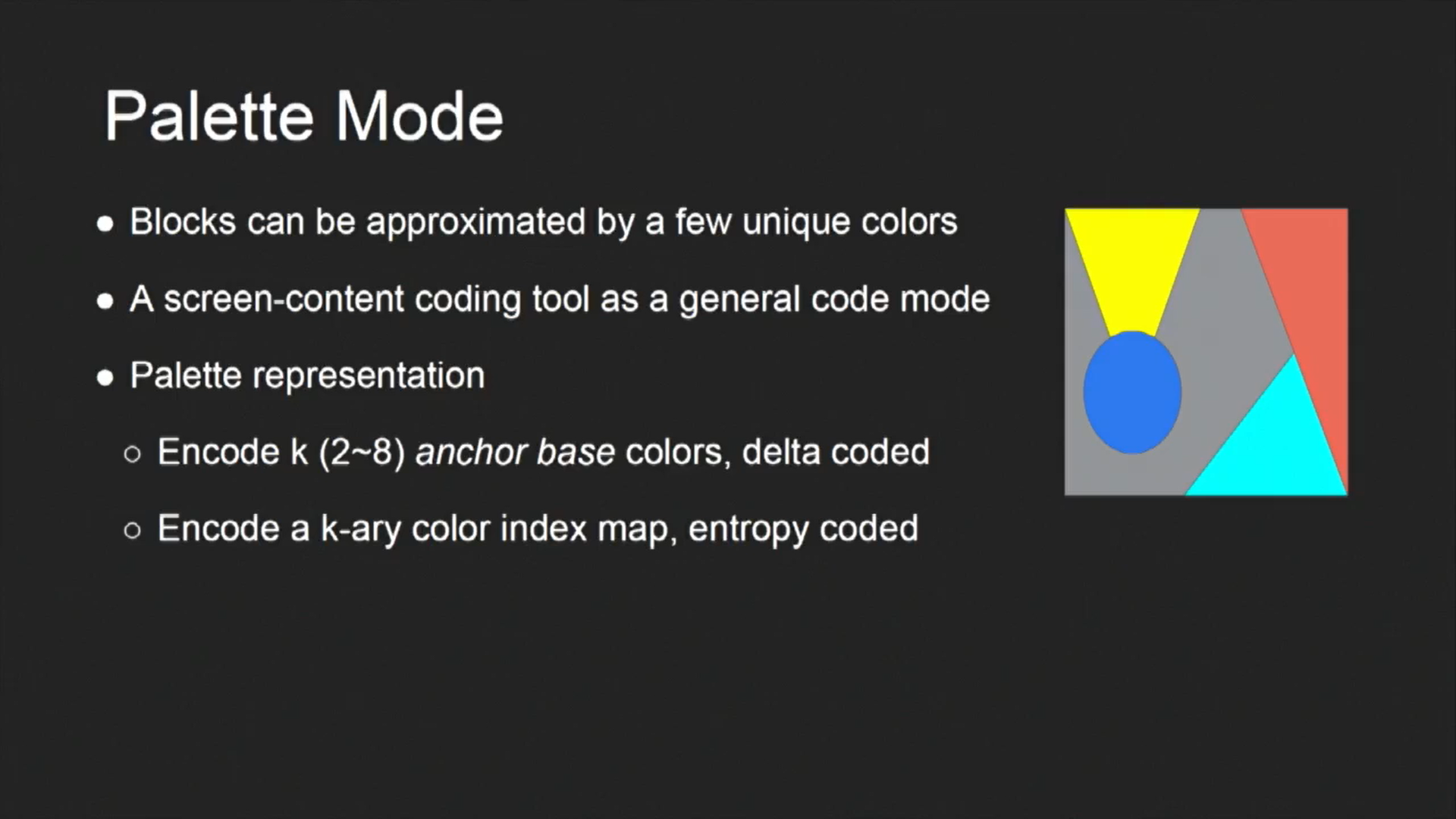
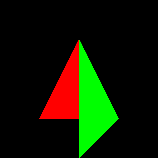
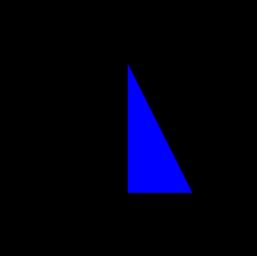
下图是采用Blender中的cycles物理渲染器渲染的坦克效果图,如果完全用CPU来计算,速度很慢,大概需要几十分钟。

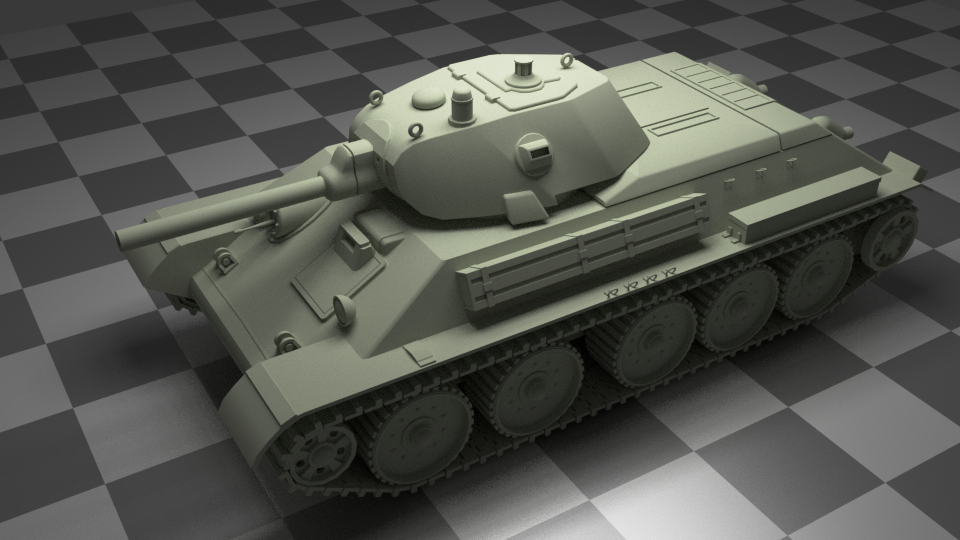
0x2 Escher是如何做到物理渲染的?

Escher是Google下一代操作系统Fuchsia上内置的基于物理的真实感渲染引擎,它和Scenic一起提供了Fuchsia上的合成及进一步特效处理功能。

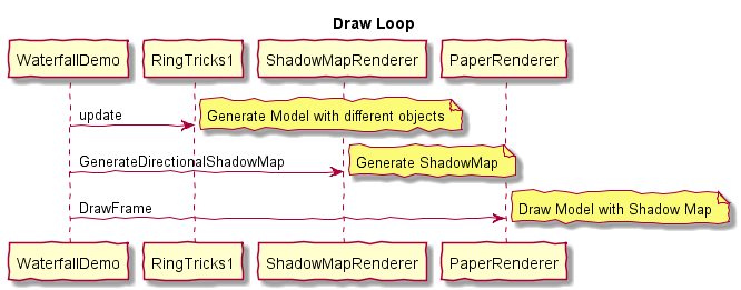
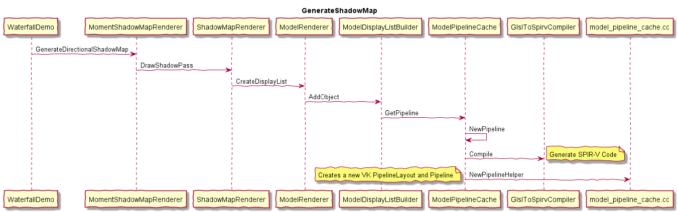
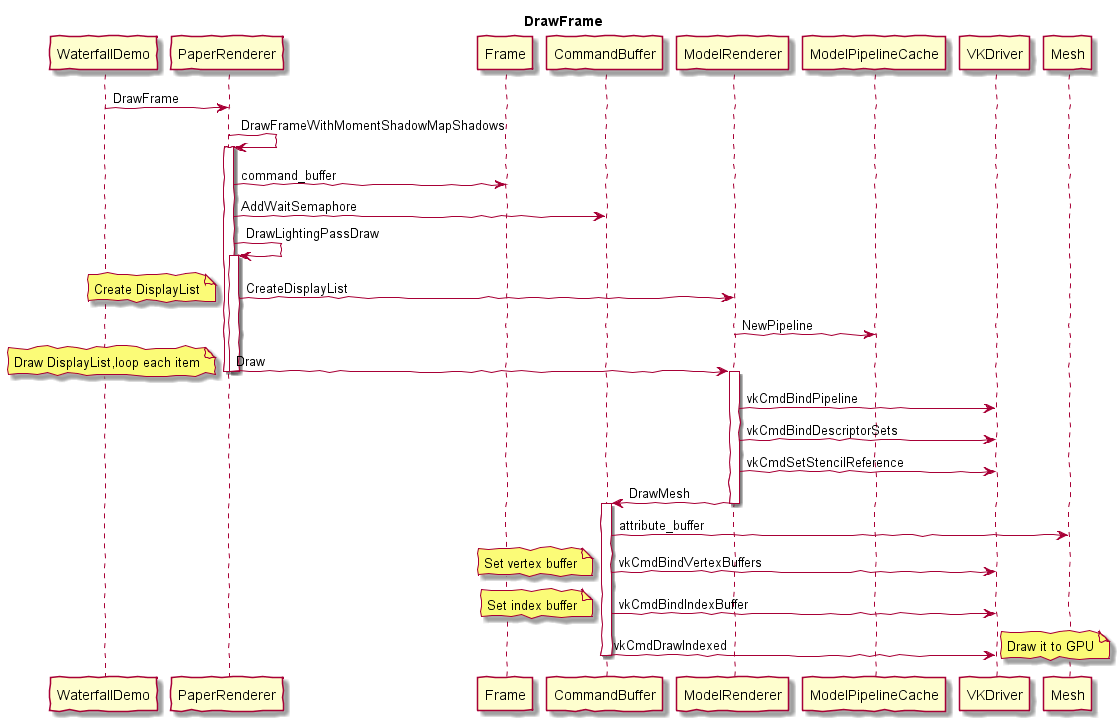
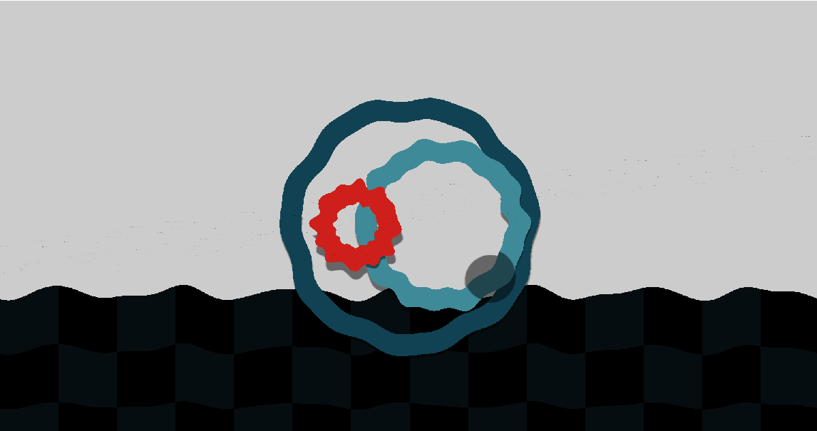
Escher目前看来主要采用光照和阴影技术来达到物理渲染的效果。

阴影是真实感渲染的一个重要组成部分,它对增加渲染物体的表面细节,帮助观察者增加对场景的空间感,从而更好地来判断物体的位置关系以及形状等有很大的帮助。可以说没有了阴影,3D场景中的真实感和吸引力将降低。

Escher中包括了如下几种阴影技术,ShadowMap、ShadowVolume等。

从Escher的实现代码可知,Escher还只是实现了部分物理渲染的功能,主要是通过light和shadow来体现真实感效果,后续要支持AR/VR中更多酷炫效果的话,需要进一步开发。

0x03 展望

随着GPU硬件中增加了Ray tracing的功能,主流API都增加了对Ray tracing的支持,未来Escher中可能会直接调用这些API(目前Escher中是调用了Vulkan,也就是说会调用Vulkan的Ray tracing支持)来加速Ray tracing的处理。

下来介绍一种主流API对 ray tracing的支持

0x31 Directx raytracing

DirectX Raytracing在DirectX 12 API的基础上引入了下面这些概念
DirectX Raytracing

What is DirectX Raytracing?
At the highest level, DirectX Raytracing (DXR) introduces four, new concepts to the DirectX 12 API:

The acceleration structure is an object that represents a full 3D environment in a format optimal for traversal by the GPU. Represented as a two-level hierarchy, the structure affords both optimized ray traversal by the GPU, as well as efficient modification by the application for dynamic objects.

A new command list method, DispatchRays, which is the starting point for tracing rays into the scene. This is how the game actually submits DXR workloads to the GPU.

A set of new HLSL shader types including ray-generation, closest-hit, any-hit, and miss shaders. These specify what the DXR workload actually does computationally. When DispatchRays is called, the ray-generation shader runs. Using the new TraceRay intrinsic function in HLSL, the ray generation shader causes rays to be traced into the scene. Depending on where the ray goes in the scene, one of several hit or miss shaders may be invoked at the point of intersection. This allows a game to assign each object its own set of shaders and textures, resulting in a unique material.

The raytracing pipeline state, a companion in spirit to today’s Graphics and Compute pipeline state objects, encapsulates the raytracing shaders and other state relevant to raytracing workloads.

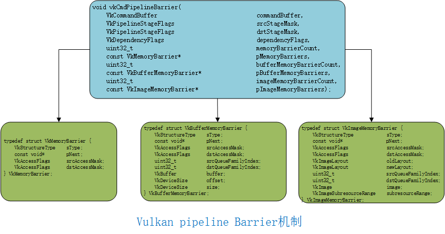
0x32 Vulkan ray tracing

NVIDIA提供了Vulkan的扩展了支持ray tracing。
Vulkan ray tracing

0x33 Metal ray tracing

Metal提供了ray tracing的支持。
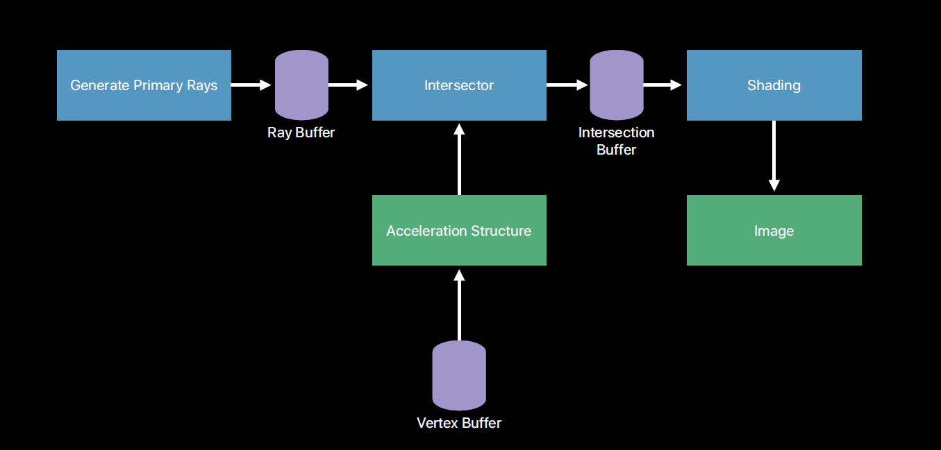
详细信息请参考
Metal ray tracing

AV1-syntax-explanation

发表于 2019-03-16 | 阅读次数

0x1 解码流程介绍


解码流程说明如下

0x11 tile_group_obu

对tile group的每个tile调用decode_tile()进行解码,直至tile group中包括的tile都解码完成.

1
2
3
4
5
6
7
for ( TileNum = tg_start; TileNum <= tg_end; TileNum++ ) {
tileRow = TileNum / TileCols
tileCol = TileNum % TileCols
......
decode_tile( )
exit_symbol( )
}

0x12 decode_tile

对tile中包含的每个partition进行解码。

1
2
3
4
5
6
for ( r = MiRowStart; r < MiRowEnd; r += sbSize4 ) {
for ( c = MiColStart; c < MiColEnd; c += sbSize4 ) {
......
decode_partition( r, c, sbSize )
}
}

0x13 decode_partition

每个partition的解码过程就是对一个super block(super block的定义参考0x2)进行解码的过程.
根据partition类型对进一步split, 不能split的类型调用decode_block().

partition类型的定义如下

| Partition index | Type of partition  |
|:-------:|:------------- |
| 0 |PARTITION_NONE|
| 1 |PARTITION_HORZ|
| 2 |PARTITION_VERT|
| 3 |PARTITION_SPLIT|
| 4 |PARTITION_HORZ_A|
| 5 |PARTITION_HORZ_B|
| 6 |PARTITION_VERT_A|
| 7 |PARTITION_VERT_B|
| 8 |PARTITION_HORZ_4|
| 9 |PARTITION_VERT_4|
1
2
3
4
5
6
7
8
9
10
11
12
13
14
15
16
17
18
19
20
21
22
23
24
25
26
27
28
29
30
31
32
33
34
35
36
37
38
39
40
41
42
43
44
if ( partition == PARTITION_NONE ) {
decode_block( r, c, subSize )
} else if ( partition == PARTITION_HORZ ) {
decode_block( r, c, subSize )
if ( hasRows )
decode_block( r + halfBlock4x4, c, subSize )
} else if ( partition == PARTITION_VERT ) {
decode_block( r, c, subSize )
if ( hasCols )
decode_block( r, c + halfBlock4x4, subSize )
} else if ( partition == PARTITION_SPLIT ) {
decode_partition( r, c, subSize )
decode_partition( r, c + halfBlock4x4, subSize )
decode_partition( r + halfBlock4x4, c, subSize )
decode_partition( r + halfBlock4x4, c + halfBlock4x4, subSize )
} else if ( partition == PARTITION_HORZ_A ) {
decode_block( r, c, splitSize )
decode_block( r, c + halfBlock4x4, splitSize )
decode_block( r + halfBlock4x4, c, subSize )
} else if ( partition == PARTITION_HORZ_B ) {
decode_block( r, c, subSize )
decode_block( r + halfBlock4x4, c, splitSize )
decode_block( r + halfBlock4x4, c + halfBlock4x4, splitSize )
} else if ( partition == PARTITION_VERT_A ) {
decode_block( r, c, splitSize )
decode_block( r + halfBlock4x4, c, splitSize )
decode_block( r, c + halfBlock4x4, subSize )
} else if ( partition == PARTITION_VERT_B ) {
decode_block( r, c, subSize )
decode_block( r, c + halfBlock4x4, splitSize )
decode_block( r + halfBlock4x4, c + halfBlock4x4, splitSize )
} else if ( partition == PARTITION_HORZ_4 ) {
decode_block( r + quarterBlock4x4 * 0, c, subSize )
decode_block( r + quarterBlock4x4 * 1, c, subSize )
decode_block( r + quarterBlock4x4 * 2, c, subSize )
if ( r + quarterBlock4x4 * 3 < MiRows )
decode_block( r + quarterBlock4x4 * 3, c, subSize )
} else { //PARTITION_VERT_4
decode_block( r, c + quarterBlock4x4 * 0, subSize )
decode_block( r, c + quarterBlock4x4 * 1, subSize )
decode_block( r, c + quarterBlock4x4 * 2, subSize )
if ( c + quarterBlock4x4 * 3 < MiCols )
decode_block( r, c + quarterBlock4x4 * 3, subSize )
}

0x14 decode_block

对一个block进行解码,进一步调用residual对残差进行解码.

0x15 transform_tree

对不同size的transform块进行解码,它是一个递归函数,递归退出函数是transform_block.

1
2
3
4
5
6
7
8
9
10
11
12
13
14
15
16
17
18
19
20
21
22
23
24
25
26
27
28
29
transform_tree( startX, startY, w, h ) { Type
maxX = MiCols * MI_SIZE
maxY = MiRows * MI_SIZE
if ( startX >= maxX || startY >= maxY ) {
return
}
row = startY >> MI_SIZE_LOG2
col = startX >> MI_SIZE_LOG2
lumaTxSz = InterTxSizes[ row ][ col ]
lumaW = Tx_Width[ lumaTxSz ]
lumaH = Tx_Height[ lumaTxSz ]
if ( w <= lumaW && h <= lumaH ) {
txSz = find_tx_size( w, h )
transform_block( 0, startX, startY, txSz, 0, 0 )
} else {
if ( w > h ) {
transform_tree( startX, startY, w/2, h )
transform_tree( startX + w / 2, startY, w/2, h )
} else if ( w < h ) {
transform_tree( startX, startY, w, h/2 )
transform_tree( startX, startY + h/2, w, h/2 )
} else {
transform_tree( startX, startY, w/2, h/2 )
transform_tree( startX + w/2, startY, w/2, h/2 )
transform_tree( startX, startY + h/2, w/2, h/2 )
transform_tree( startX + w/2, startY + h/2, w/2, h/2 )
}
}
}

0x16 Reconstruct中包括具体的反量化,反dct,重建像素和loop filter等过程.

0x2 super block

下图说明了一个frame由许多super block组成,super block的定义稍后说明.

Super block的定义如下
The top level of the block quadtree within a tile. All superblocks within a frame are the same size and are square. The
superblocks may be 128x128 luma samples or 64x64 luma samples. A superblock may contain 1 or 2 or 4 mode info
blocks, or may be bisected in each direction to create 4 sub-blocks, which may themselves be further subpartitioned,
forming the block quadtree.

通过在sequence_header_obu中的use_128x128_superblock来控制superblock的大小是128x128还是64x64.
sequence_header_obu( ) {
……
use_128x128_superblock f(1)
……
}

use_128x128_superblock的定义如下
when equal to 1, indicates that superblocks contain 128x128 luma samples. When equal to 0,
it indicates that superblocks contain 64x64 luma samples.

0x3 split划分

下图显示了super block(64x64)的split状态, 从图中可以看到,64x64的block会被split到32x32,再进一步split到16x16.

0x4 Intra Y mode

下图显示了Intra Prediction中Y分量的mode,不同的颜色代码不同的mode.

0x5 Intra UV mode

下图显示了Intra Prediction中UV分量的mode,不同的颜色代码不同的mode,其中显示数字的块表示该mode为chroma from luma prediction, 其中显示的数字表示chroma需要从哪个位置的luma预测.

0x6 Motion vector

下图显示了Inter frame帧间预测的运动向量.

0x7 Reference

AV1 analyzer

Synchronization-in-Vulkan

发表于 2019-03-09 | 阅读次数

0x1 Overview

Vulkan的一大优势是能通过多线程来提升CPU bounding场景的performance,这依赖于其提供了下面几种同步机制。

Semaphores,用于多个queue之间的同步或者是一个queue的任务提交同步。
Events,用于一个command buffer内部的同步或在同一个queue内部多个command buffer的同步。
Fences,用于提供devive和host之间的同步。
barriers,用于精确控制pipeline中各个pipeline阶段的资源流动。
下图说明了这几种同步机制适用的场景。

0x2 Details

0x21 Pipeline Barrier

Barrier是一种同步机制,用来管理内存访问和同步Vulkan pipeline中各个阶段里的资源状态变化。通过这种机制来fine-grained控制command buffer执行过程中资源在pipeline的各个阶段中的流动。

Vulkan通过API vkCmdPipelineBarrier()来控制三种barrier操作,Memory barrier, Buffer Memory barrier和Image Memory barrier。

其中Memory barrier, Buffer Memory barrier会控制资源在pipeline各个阶段的执行次序。其作用有两个,
一个作用是控制执行顺序,对写后读(WaR),读后写(RaW),写后写(WaW)三种情况提供保护。另外一个作用是保证pipeline不同部分中数据的视图的一致性,因为pipeline不同stage之间可能有cache,在插入了barrier的地方需要flush cache。
Image Memory barrier的作用是控制对图像的访问。

三种barrier的数据结构如下所示

Vulkan的pipeline包括下面这几种,Command的执行从top开始,然后执行类似VS,FS之类的pipeline,最后是bottom。

1
2
3
4
5
6
7
8
9
10
11
12
13
14
TOP_OF_PIPE_BIT
DRAW_INDIRECT_BIT
VERTEX_INPUT_BIT
VERTEX_SHADER_BIT
TESSELLATION_CONTROL_SHADER_BIT
TESSELLATION_EVALUATION_SHADER_BIT
GEOMETRY_SHADER_BIT
FRAGMENT_SHADER_BIT
EARLY_FRAGMENT_TESTS_BIT
LATE_FRAGMENT_TESTS_BIT
COLOR_ATTACHMENT_OUTPUT_BIT
TRANSFER_BIT
COMPUTE_SHADER_BIT
BOTTOM_OF_PIPE_BIT

但是如何设置vkCmdPipelineBarrier中source stage和dest stage呢?

最简单的方式是把source stage设置为VK_PIPELINE_STAGE_BOTTOM_OF_PIPE_BIT,dest stage设置为VK_PIPELINE_STAGE_TOP_OF_PIPE_BIT。
这种设置会等待前面command buffer的所有pipeline都执行结束了,后面command buffer才能开始,很明显这种设置多个command buffer没有并行执行,command buffer之间只是串行的,performance应该会受到影响。

如果希望能在多个command buffer之间并行执行,需要根据实际情况设置source stage和dest stage。

假如vertex shader后面接了一个compute shader, compute shader执行的时候需要读取vertex shader的执行结果,
我们可以把source stage设置为VK_PIPELINE_STAGE_VERTEX_SHADER_BIT,dest stage设置为VK_PIPELINE_STAGE_COMPUTE_SHADER_BIT。
更详细的介绍,请参考后面的代码说明。

原则上source stage和dest stage的设置应该尽量使下图中的ubblocked pipeline(green stages)尽可能地多,这样并行度会越高。

Memory barrier示例代码

根据需要,创建两个queue(graphics queue和compute queue)和对应的command buffer.

1
2
3
4
5
6
7
8
9
10
11
12
13
14
15
16
17
// 创建graphics queue和command pool
vkGetDeviceQueue(device, vulkanDevice->queueFamilyIndices.graphics, 0, &queue);
VkCommandPoolCreateInfo cmdPoolInfo = {};
cmdPoolInfo.sType = VK_STRUCTURE_TYPE_COMMAND_POOL_CREATE_INFO;
cmdPoolInfo.queueFamilyIndex = vulkanDevice->queueFamilyIndices.graphics;
cmdPoolInfo.flags = VK_COMMAND_POOL_CREATE_RESET_COMMAND_BUFFER_BIT;
VK_CHECK_RESULT(vkCreateCommandPool(device, &cmdPoolInfo, nullptr, &cmdPool));
// 创建compute queue和command pool
vkGetDeviceQueue(device, vulkanDevice->queueFamilyIndices.compute, 0, &compute.queue);
VkCommandPoolCreateInfo cmdPoolInfo = {};
cmdPoolInfo.sType = VK_STRUCTURE_TYPE_COMMAND_POOL_CREATE_INFO;
cmdPoolInfo.queueFamilyIndex = vulkanDevice->queueFamilyIndices.compute;
cmdPoolInfo.flags = VK_COMMAND_POOL_CREATE_RESET_COMMAND_BUFFER_BIT;
VK_CHECK_RESULT(vkCreateCommandPool(device, &cmdPoolInfo, nullptr, &compute.commandPool));

下面的代码说明了如何在这两个command buffer执行的过程中插入barrier, 从而实现资源访问的控制。

1
2
3
4
5
6
7
8
9
10
11
12
13
14
15
16
17
18
19
20
21
22
23
24
25
26
27
28
29
30
31
32
33
34
35
36
37
38
39
40
41
42
43
44
45
46
47
48
49
50
51
52
53
54
55
56
void buildComputeCommandBuffer()
{
VkCommandBufferBeginInfo cmdBufInfo = vks::initializers::commandBufferBeginInfo();
VK_CHECK_RESULT(vkBeginCommandBuffer(compute.commandBuffer, &cmdBufInfo));
// Compute particle movement
// Add memory barrier to ensure that the (graphics) vertex shader has fetched attributes before compute starts to write to the buffer
VkBufferMemoryBarrier bufferBarrier = vks::initializers::bufferMemoryBarrier();
bufferBarrier.buffer = compute.storageBuffer.buffer;
bufferBarrier.size = compute.storageBuffer.descriptor.range;
bufferBarrier.srcAccessMask = VK_ACCESS_VERTEX_ATTRIBUTE_READ_BIT; // Vertex shader invocations have finished reading from the buffer
bufferBarrier.dstAccessMask = VK_ACCESS_SHADER_WRITE_BIT; // Compute shader wants to write to the buffer
// Compute and graphics queue may have different queue families (see VulkanDevice::createLogicalDevice)
// For the barrier to work across different queues, we need to set their family indices
bufferBarrier.srcQueueFamilyIndex = vulkanDevice->queueFamilyIndices.graphics; // Required as compute and graphics queue may have different families
bufferBarrier.dstQueueFamilyIndex = vulkanDevice->queueFamilyIndices.compute; // Required as compute and graphics queue may have different families
vkCmdPipelineBarrier(
compute.commandBuffer,
VK_PIPELINE_STAGE_VERTEX_SHADER_BIT,
VK_PIPELINE_STAGE_COMPUTE_SHADER_BIT,
VK_FLAGS_NONE,
0, nullptr,
1, &bufferBarrier,
0, nullptr);
vkCmdBindPipeline(compute.commandBuffer, VK_PIPELINE_BIND_POINT_COMPUTE, compute.pipeline);
vkCmdBindDescriptorSets(compute.commandBuffer, VK_PIPELINE_BIND_POINT_COMPUTE, compute.pipelineLayout, 0, 1, &compute.descriptorSet, 0, 0);
// Dispatch the compute job
vkCmdDispatch(compute.commandBuffer, PARTICLE_COUNT / 256, 1, 1);
// Add memory barrier to ensure that compute shader has finished writing to the buffer
// Without this the (rendering) vertex shader may display incomplete results (partial data from last frame)
bufferBarrier.srcAccessMask = VK_ACCESS_SHADER_WRITE_BIT; // Compute shader has finished writes to the buffer
bufferBarrier.dstAccessMask = VK_ACCESS_VERTEX_ATTRIBUTE_READ_BIT; // Vertex shader invocations want to read from the buffer
bufferBarrier.buffer = compute.storageBuffer.buffer;
bufferBarrier.size = compute.storageBuffer.descriptor.range;
// Compute and graphics queue may have different queue families (see VulkanDevice::createLogicalDevice)
// For the barrier to work across different queues, we need to set their family indices
bufferBarrier.srcQueueFamilyIndex = vulkanDevice->queueFamilyIndices.compute; // Required as compute and graphics queue may have different families
bufferBarrier.dstQueueFamilyIndex = vulkanDevice->queueFamilyIndices.graphics; // Required as compute and graphics queue may have different families
vkCmdPipelineBarrier(
compute.commandBuffer,
VK_PIPELINE_STAGE_COMPUTE_SHADER_BIT,
VK_PIPELINE_STAGE_VERTEX_SHADER_BIT,
VK_FLAGS_NONE,
0, nullptr,
1, &bufferBarrier,
0, nullptr);
vkEndCommandBuffer(compute.commandBuffer);
}

Image barrier示例代码如下

1
2
3
4
5
6
7
8
9
10
11
12
13
14
15
16
17
18
19
20
21
22
23
24
25
26
27
28
29
30
31
32
33
34
35
36
37
38
39
40
41
42
43
44
45
46
47
48
49
50
51
52
53
54
55
for (int32_t i = 0; i < drawCmdBuffers.size(); ++i)
{
// Set target frame buffer
renderPassBeginInfo.framebuffer = frameBuffers[i];
VK_CHECK_RESULT(vkBeginCommandBuffer(drawCmdBuffers[i], &cmdBufInfo));
// Image memory barrier to make sure that compute shader writes are finished before sampling from the texture
VkImageMemoryBarrier imageMemoryBarrier = {};
imageMemoryBarrier.sType = VK_STRUCTURE_TYPE_IMAGE_MEMORY_BARRIER;
// We won't be changing the layout of the image
imageMemoryBarrier.oldLayout = VK_IMAGE_LAYOUT_GENERAL;
imageMemoryBarrier.newLayout = VK_IMAGE_LAYOUT_GENERAL;
imageMemoryBarrier.image = textureComputeTarget.image;
imageMemoryBarrier.subresourceRange = { VK_IMAGE_ASPECT_COLOR_BIT, 0, 1, 0, 1 };
imageMemoryBarrier.srcAccessMask = VK_ACCESS_SHADER_WRITE_BIT;
imageMemoryBarrier.dstAccessMask = VK_ACCESS_SHADER_READ_BIT;
vkCmdPipelineBarrier(
drawCmdBuffers[i],
VK_PIPELINE_STAGE_COMPUTE_SHADER_BIT,
VK_PIPELINE_STAGE_FRAGMENT_SHADER_BIT,
VK_FLAGS_NONE,
0, nullptr,
0, nullptr,
1, &imageMemoryBarrier);
vkCmdBeginRenderPass(drawCmdBuffers[i], &renderPassBeginInfo, VK_SUBPASS_CONTENTS_INLINE);
VkViewport viewport = vks::initializers::viewport((float)width * 0.5f, (float)height, 0.0f, 1.0f);
vkCmdSetViewport(drawCmdBuffers[i], 0, 1, &viewport);
VkRect2D scissor = vks::initializers::rect2D(width, height, 0, 0);
vkCmdSetScissor(drawCmdBuffers[i], 0, 1, &scissor);
VkDeviceSize offsets[1] = { 0 };
vkCmdBindVertexBuffers(drawCmdBuffers[i], VERTEX_BUFFER_BIND_ID, 1, &vertexBuffer.buffer, offsets);
vkCmdBindIndexBuffer(drawCmdBuffers[i], indexBuffer.buffer, 0, VK_INDEX_TYPE_UINT32);
// Left (pre compute)
vkCmdBindDescriptorSets(drawCmdBuffers[i], VK_PIPELINE_BIND_POINT_GRAPHICS, graphics.pipelineLayout, 0, 1, &graphics.descriptorSetPreCompute, 0, NULL);
vkCmdBindPipeline(drawCmdBuffers[i], VK_PIPELINE_BIND_POINT_GRAPHICS, graphics.pipeline);
vkCmdDrawIndexed(drawCmdBuffers[i], indexCount, 1, 0, 0, 0);
// Right (post compute)
vkCmdBindDescriptorSets(drawCmdBuffers[i], VK_PIPELINE_BIND_POINT_GRAPHICS, graphics.pipelineLayout, 0, 1, &graphics.descriptorSetPostCompute, 0, NULL);
vkCmdBindPipeline(drawCmdBuffers[i], VK_PIPELINE_BIND_POINT_GRAPHICS, graphics.pipeline);
viewport.x = (float)width / 2.0f;
vkCmdSetViewport(drawCmdBuffers[i], 0, 1, &viewport);
vkCmdDrawIndexed(drawCmdBuffers[i], indexCount, 1, 0, 0, 0);
vkCmdEndRenderPass(drawCmdBuffers[i]);
VK_CHECK_RESULT(vkEndCommandBuffer(drawCmdBuffers[i]));
}

0x22 Semaphore/Event/Fence

下面说明并行渲染多帧时采用的同步机制。

如上图所示,当swap chain中的image可用时,vkAcquireNextImageKHR会触发一个semaphore a,vkQueueSubmit拿到这个semaphore b以后开始执行command buffer的命令,执行command buffer的过程中会往vkAcquireNextImageKHR得到的image(这个image类似于frame buffer的概念)中写内容,执行完毕以后会触发semaphore b, vkQueuePresentKHR等待这个semaphore b触发以后就把image的内容绘制到display上。
当第N frame在Submit任务到GPU上执行的时候, (N+1)frame同时在CPU上开启多线程往多个command buffer中生成command,这样CPU和GPU相互配合,提升performance。

下面说明渲染一帧时内部采用的同步机制。

上图中第一个vkQueueSubmit的参数如下

1
2
3
4
5
6
7
8
9
10
submitInfo.waitSemaphoreCount = 1;
// 执行vkQueueSubmit的wait semaphore,等待其触发,其已经在vkAcquireNextImageKHR中触发
submitInfo.pWaitSemaphores = &semaphores.presentComplete;
submitInfo.signalSemaphoreCount = 1;
// vkQueueSubmit执行完以后的signal semaphore
submitInfo.pSignalSemaphores = &semaphores.renderComplete;
submitInfo.commandBufferCount = 1;
submitInfo.pCommandBuffers = &primaryCommandBuffer;
VK_CHECK_RESULT(vkQueueSubmit(queue, 1, &submitInfo, renderFence));

然后执行vKQueuePresentKHR,这边的wait semaphore是前面一步的renderComplete, 表明只有renderComplete被触发以后vKQueuePresentKHR才能被执行。

1
VK_CHECK_RESULT(swapChain.queuePresent(queue, currentBuffer, submitTextOverlay ? semaphores.textOverlayComplete : semaphores.renderComplete));

上面虚线部分表明在执行vKQueuePresentKHR之间,还有一个text overlay command buffer需要执行。
这个command buffer的wait semaphore为renderComplete。

1
2
3
4
5
6
7
8
9
10
11
12
// Set semaphores
// Wait for render complete semaphore
submitInfo.waitSemaphoreCount = 1;
submitInfo.pWaitSemaphores = &semaphores.renderComplete;
// Signal ready with text overlay complete semaphpre
submitInfo.signalSemaphoreCount = 1;
submitInfo.pSignalSemaphores = &semaphores.textOverlayComplete;
// Submit current text overlay command buffer
submitInfo.commandBufferCount = 1;
submitInfo.pCommandBuffers = &textOverlay->cmdBuffers[currentBuffer];
VK_CHECK_RESULT(vkQueueSubmit(queue, 1, &submitInfo, VK_NULL_HANDLE));

0x3 References

Vulkan barriers explained
Multi-Threading in Vulkan

The overview of AV1 coding

发表于 2019-03-02 | 阅读次数

0x1 Overview

AOMedia Video 1 (AV1) is an open, royalty-free video coding format, it was in particular motivated by the high cost and uncertainty of HEVC patent licensing, it aims to provide royalty-free and high compression ratio video codec.

This blog will give us the overview of AV1 codec, this material is from the internet, you can find the link url in the reference part.

ovewview

ovewview

0x2 Partition

0x3 Intra Prediction

0x04 Inter Prediction

0x05 Transform coding

0x06 Quantization

0x7 Entropy coding

0x8 Filter

0x8 Efficiency and Complexity

0x9 Reference

a technial overview of the AV1
The AV1 Video Codec
AV1 wiki

How stencil buffer work in graphics pipeline

发表于 2019-02-23 | 阅读次数

0x1 总体介绍

下图是Stencil Test在在post fragment pipeline中的位置。
post_shader_fragment_pipeline

Stencil Test的作用可以把绘制限定在特定的区域,这点和scissor test类似,但是stencil test支持不规则的区域,而scissor test做不到这一点。

Stencil Test是通过stencil buffer中记录的模板信息来完成的,stencil buffer中保存着每个位置的fragment对应的mask值,当graphics pipeline执行stencil test的时候,把通过api设定的模板参考值与相应位置的fragment对应的mask值进行比较,如果不符合条件则被丢弃,反之则进行绘制。

Stencil Test的使用可以看成两步操作,第一步是生成stencil buffer,通过渲染几何体并指定stencil buffer的更新方式来实现。第二步是使用stencil buffer中的内容来控制最终颜色缓存区的渲染。

0x2 从GPU硬件的角度理解Stencil test

下面介绍Stencil test是如何在gpu hardware pipeline中执行的。

下图是broadcom v3d system block图。

v3d是tile buffer rendering的gpu,其渲染分成两个阶段,第一阶段是计算出每个tile中有哪些triangle需要绘制,第二阶段是遍历所有的tile,对每个tile执行真正的绘制工作。

如下图所示,stencil buffer是gpu hardware中tile buffer的一部分,这是gpu硬件中单独的一块buffer,用来保存当前渲染过程中使用到的stencil值。

在每个tile的绘制过程中,都需要根据tile坐标取得stencil buffer中对应的stencil mask, 然后执行stencil test, 执行完了以后,如果必要,还需要更新stencil buffer中对应的stencil值。

v3d system block

0x3 Stencil test测试程序

这个Stencil test测试程序分成两步操作。

第一步只是生成stencil buffer的内容,该过程不输出color,只更新stencil buffer的内容。

更新stencil buffer的策略通过下面的api来控制。
glStencilOp(GL_KEEP, GL_INCR, GL_INCR);

第一个参数是stencil test fail的时候更新stencil buffer的操作,这里的GL_KEEP表明stencil test fail时不对stencil buffer进行更新。

第二个参数表明stencil test pass但depth test fail的时候更新stencil buffer的操作,这里的GL_INCR表明此时对stencil buffer的相应位加1.

第三个参数表明stencil test pass而且depth test pass的时候更新stencil buffer的操作,这里的GL_INCR表明此时对stencil buffer的相应位加1.

以上的设置表明只要stencil test pass的话就对stencil buffer的相应位加1,不管depth test是pass或者fail.

绘制triangle1的代码

1
2
3
4
5
6
7
8
9
10
11
12
13
14
15
16
glEnable(GL_STENCIL_TEST);
glStencilFunc(GL_ALWAYS, 0, 0);
glStencilOp(GL_KEEP, GL_INCR, GL_INCR);
glColorMask(GL_FALSE, GL_FALSE, GL_FALSE, GL_FALSE);
glUseProgram(gProgram);
// draw triangle 1
glVertexAttribPointer(gfPositionHandle, 3, GL_FLOAT, GL_FALSE,
TRIANGLE_VERTICES_DATA_STRIDE_BYTES, gTriangleVerticesData);
glEnableVertexAttribArray(gfPositionHandle);
glUniform4fv(gfColor, 1, gColor);
glDrawArrays(GL_TRIANGLES, 0, 3);

绘制triangle2的代码

1
2
3
4
5
6
7
8
9
// draw triangl2
glVertexAttribPointer(gfPositionHandle, 3, GL_FLOAT, GL_FALSE,
TRIANGLE_VERTICES_DATA_STRIDE_BYTES, gTriangleVerticesData1);
glEnableVertexAttribArray(gfPositionHandle);
glUniform4fv(gfColor, 1, gColor1);
glDrawArrays(GL_TRIANGLES, 0, 3);

第二步是根据stencil buffer中的内容为mask来绘制triangle1和triangle2的重叠区域,这个时候发送给opengles的绘制区域可以设置成整个屏幕的大小,但是只有相应的位符合stencil buffer中的条件才能使stencil test通过,这个时候才能输出color。

这个控制相应的位符合stencil buffer中条件的代码如下所示,也就是说stencil buffer相应的位的值需要为0x02,也就是说这个点绘制过两次(triangle1和triangle2都绘制过)。

glStencilFunc(GL_NOTEQUAL, 0, 0xf8 | 0x02);

1
2
3
4
5
6
7
8
9
10
11
12
13
14
15
16
glDisable(GL_DEPTH_TEST);
glStencilOp(GL_KEEP, GL_KEEP, GL_KEEP);
glVertexAttribPointer(gfPositionHandle, 3, GL_FLOAT, GL_FALSE,
TRIANGLE_VERTICES_DATA_STRIDE_BYTES, gTriangleVerticesData2);
glEnableVertexAttribArray(gfPositionHandle);
glUniform4fv(gfColor, 1, gColor2);
// draw the area with blue color
glColorMask(GL_FALSE, GL_FALSE, GL_TRUE, GL_FALSE);
glStencilFunc(GL_NOTEQUAL, 0, 0xf8 | 0x02);
glDrawArrays(GL_TRIANGLE_STRIP, 0, 4);

0x4 程序运行效果

triangle1单独绘制的效果
draw_triangle1

triangle2单独绘制的效果
draw_triangle2

triangle1和triangle2同时绘制的效果
draw_triangle1_triangle2

triangle1和triangle2同时绘制但不更新color buffer, 然后根据stencil buffer绘制triangle1和triangle2相交区域的效果
drawing_with_stencil_buffer

Mesh support in escher

发表于 2019-02-16 | 阅读次数

0x1 总体介绍

Graphics中各种图形的渲染是通过许多小的三角形的渲染拼接组成的,Mesh的过程是把需要渲染的图形划分成许多小三角形的过程.
Escher中的mesh过程需要把Rectangle, Circle, Ring, Sphere等形状的显示对象划分成小三角形,然后把小三角形的数据通过Vulkan API来驱动GPU显示.

下图是escher中mesh相关类的类图

mesh_class_diagram

下面简单介绍一下这些类

Mesh创建过程中,
MeshBuilder根据MeshSpec的设置生成对应的Mesh.
Mesh的vertex/index数据保存到CommandBuffer中,

Mesh渲染过程中,
对应的PageRenderer生成对应的Object,每一个Object都有对应的Mesh,这些Object挂接到Model下面.
然后根据Model中包含的Mesh生成ModelDisplayList,然后遍历这个ModelDisplayList,把Mesh中的vertex/index数据传入CommandBuffer中,从而让GPU渲染的时候能够访问到这些数据.

0x2 各种shape的mesh过程

0x21 MeshBuilder介绍

MeshBuilder提供接口把vertex data和index data保存起来.

其中保存的数据结构如下,
vertex_stagingbuffer保存vertex数据,index_stagingbuffer保存index数据.
vertex_stagingbuffer和index_stagingbuffer的内存空间是通过GpuUploader::Writer来分配的.

1
2
3
4
5
6
7
const size_t max_vertex_count_;
const size_t max_index_count_;
const size_t vertex_stride_;
uint8_t* vertex_staging_buffer_;
uint32_t* index_staging_buffer_;
size_t vertex_count_ = 0;
size_t index_count_ = 0;

下面是其提供设置vertex data和index data的接口.
注意下面的接口都返回 *this, 这是为了链式表达式的需要.

1
2
3
4
5
6
7
8
9
10
11
12
13
14
15
16
17
18
19
inline MeshBuilder& MeshBuilder::AddIndex(uint32_t index) {
FXL_DCHECK(index_count_ < max_index_count_);
index_staging_buffer_[index_count_++] = index;
return *this;
}
inline MeshBuilder& MeshBuilder::AddVertexData(const void* ptr, size_t size) {
FXL_DCHECK(vertex_count_ < max_vertex_count_);
FXL_DCHECK(size <= vertex_stride_);
size_t offset = vertex_stride_ * vertex_count_++;
memcpy(vertex_staging_buffer_ + offset, ptr, size);
return *this;
}
template <typename VertexT>
MeshBuilder& MeshBuilder::AddVertex(const VertexT& v) {
AddVertexData(&v, sizeof(VertexT));
return *this;
}

然后调用Build()接口生成mesh对象.

0x22 SimpleRectangle

下面是生成SimpleRectangle的mesh的代码,SimpleRectangle是普通的非圆角Rectangle.
从这个代码中可以看到,该mesh过程会生成4个vertex数据,生成6个index数据(因为是2个三角形).

1
2
3
4
5
6
7
8
9
10
11
12
13
14
15
16
17
18
19
20
21
22
23
MeshPtr NewSimpleRectangleMesh(MeshBuilderFactory* factory) {
MeshSpec spec{MeshAttribute::kPosition2D | MeshAttribute::kUV};
// In each vertex, the first two floats represent the position and the second
// two are UV coordinates.
vec4 v0(0.f, 0.f, 0.f, 0.f);
vec4 v1(1.f, 0.f, 1.f, 0.f);
vec4 v2(1.f, 1.f, 1.f, 1.f);
vec4 v3(0.f, 1.f, 0.f, 1.f);
MeshBuilderPtr builder = factory->NewMeshBuilder(spec, 4, 6);
return builder->AddVertex(v0)
.AddVertex(v1)
.AddVertex(v2)
.AddVertex(v3)
.AddIndex(0)
.AddIndex(1)
.AddIndex(2)
.AddIndex(0)
.AddIndex(2)
.AddIndex(3)
.Build();
}

前面的mesh过程计算好了一个通用的SimpleRectangle的mesh信息,
具体要显示Rectangle的时候根据具体的显示位置(top_left_position.x/y/z)和显示的大小(size.x/y)来绘制Rectangle.
指定显示的位置可以理解为平移,指定显示的大小可以理解为缩放.
这个平移/缩放过程通过设置transform矩阵来实现,在shader代码中把这个矩阵和通用SimpleRectangle的vertex坐标相乘.

transform矩阵的设置过程如下

1
2
3
4
5
6
7
8
9
10
Object Object::NewRect(const vec3& top_left_position, const vec2& size,
MaterialPtr material) {
mat4 transform(1);
transform[0][0] = size.x;
transform[1][1] = size.y;
transform[3][0] = top_left_position.x;
transform[3][1] = top_left_position.y;
transform[3][2] = top_left_position.z;
return Object(transform, Shape(Shape::Type::kRect), std::move(material));
}

0x23 Rectangle

下面的代码生成普通Rectangle的Mesh,

下面函数的参数中,
subdivisions指定Rectangle的拆分数,
size指定Rectangle的大小,
top_left指定左上角的坐标,
生成mesh的时候把Rectangle分成(subdivisions*2-1)个小矩形,指定这些小矩形的vertex/index设置.

这个普通Rectangle的mesh和SimpleRectangle的mesh不同之处在于普通Rectangle的mesh是每一个Rectangle生成一个,不具有SimpleRectangle的mesh的通用性. 另外普通Rectangle的mesh会包括更多的小三角形.

1
2
3
4
5
6
7
8
9
10
11
12
13
14
15
16
17
18
19
20
21
22
23
24
25
26
27
28
29
30
31
32
33
34
35
36
37
38
39
40
41
42
43
44
45
46
47
48
49
50
51
52
53
54
55
56
57
58
59
60
61
62
MeshPtr NewRectangleMesh(MeshBuilderFactory* factory, const MeshSpec& spec,
int subdivisions, vec2 size, vec2 top_left,
float top_offset_magnitude,
float bottom_offset_magnitude) {
// Compute the number of vertices in the tessellated circle.
FXL_DCHECK(subdivisions >= 0);
size_t vertices_per_side = 2;
while (subdivisions-- > 0) {
vertices_per_side *= 2;
}
size_t vertex_count = vertices_per_side * 2;
size_t index_count = (vertices_per_side - 1) * 6;
auto builder = factory->NewMeshBuilder(spec, vertex_count, index_count);
// Generate vertex positions.
constexpr size_t kMaxVertexSize = 100;
uint8_t vertex[kMaxVertexSize];
auto vertex_p =
GetVertexAttributePointers(vertex, kMaxVertexSize, spec, builder);
FXL_CHECK(vertex_p.pos2);
const float vertices_per_side_reciprocal = 1.f / (vertices_per_side - 1);
for (size_t i = 0; i < vertices_per_side; ++i) {
// Build bottom vertex.
(*vertex_p.pos2) =
top_left + vec2(size.x * i * vertices_per_side_reciprocal, size.y);
if (vertex_p.uv)
(*vertex_p.uv) = vec2(i * vertices_per_side_reciprocal, 1.f);
if (vertex_p.pos_offset)
(*vertex_p.pos_offset) = vec2(0, 1.f * bottom_offset_magnitude);
if (vertex_p.perim)
(*vertex_p.perim) = i * vertices_per_side_reciprocal;
builder->AddVertexData(vertex, builder->vertex_stride());
// Build top vertex.
(*vertex_p.pos2) =
top_left + vec2(size.x * i * vertices_per_side_reciprocal, 0);
if (vertex_p.uv)
(*vertex_p.uv) = vec2(i * vertices_per_side_reciprocal, 0);
if (vertex_p.pos_offset)
(*vertex_p.pos_offset) = vec2(0, -1.f * top_offset_magnitude);
if (vertex_p.perim)
(*vertex_p.perim) = i * vertices_per_side_reciprocal;
builder->AddVertexData(vertex, builder->vertex_stride());
}
// Generate vertex indices.
for (size_t i = 2; i < vertex_count; i += 2) {
builder->AddIndex(i - 2);
builder->AddIndex(i - 1);
builder->AddIndex(i);
builder->AddIndex(i - 1);
builder->AddIndex(i + 1);
}
auto mesh = builder->Build();
FXL_DCHECK(mesh->num_indices() == index_count);
return mesh;
}

0x24 Circle

下面分析circle的mesh是如何生成的.

下面函数的参数中,
subdivisions指定Circle的拆分数目,
center指定Circle的中心点坐标.
radius指定Circle的半径大小.

生成mesh的时候是把Circle分成(subdivisions*4)个小扇形,然后计算这些小扇形的vertex/index设置.

1
2
3
4
5
6
7
8
9
10
11
12
13
14
15
16
17
18
19
20
21
22
23
24
25
26
27
28
29
30
31
32
33
34
35
36
37
38
39
40
41
42
43
44
45
46
47
48
49
50
51
52
53
54
55
56
57
58
59
60
61
62
63
64
65
66
67
68
69
70
71
72
MeshPtr NewCircleMesh(MeshBuilderFactory* factory, const MeshSpec& spec,
int subdivisions, vec2 center, float radius,
float offset_magnitude) {
// Compute the number of vertices in the tessellated circle.
FXL_DCHECK(subdivisions >= 0);
FXL_DCHECK(spec.IsValidOneBufferMesh());
size_t outer_vertex_count = 4;
while (subdivisions-- > 0) {
outer_vertex_count *= 2;
}
size_t vertex_count = outer_vertex_count + 1; // Add 1 for center vertex.
size_t index_count = outer_vertex_count * 3;
auto builder = factory->NewMeshBuilder(spec, vertex_count, index_count);
// Generate vertex positions.
constexpr size_t kMaxVertexSize = 100;
uint8_t vertex[kMaxVertexSize];
auto vertex_p =
GetVertexAttributePointers(vertex, kMaxVertexSize, spec, builder);
// Build center vertex.
FXL_CHECK(vertex_p.pos2);
(*vertex_p.pos2) = center;
if (vertex_p.uv)
(*vertex_p.uv) = vec2(0.5f, 0.5f);
if (vertex_p.pos_offset)
(*vertex_p.pos_offset) = vec2(0.f, 0.f);
// TODO: This is an undesirable singularity. Perhaps it would be better to
// treat circles as a ring with inner radius of zero?
if (vertex_p.perim)
(*vertex_p.perim) = 0.f;
builder->AddVertexData(vertex, builder->vertex_stride());
// Outer vertices.
const float outer_vertex_count_reciprocal = 1.f / outer_vertex_count;
const float radian_step = 2 * M_PI / outer_vertex_count;
for (size_t i = 0; i < outer_vertex_count; ++i) {
float radians = i * radian_step;
// Direction of the current vertex from the center of the circle.
vec2 dir(sin(radians), cos(radians));
(*vertex_p.pos2) = dir * radius + center;
if (vertex_p.uv)
(*vertex_p.uv) = 0.5f * (dir + vec2(1.f, 1.f));
if (vertex_p.pos_offset)
(*vertex_p.pos_offset) = dir * offset_magnitude;
if (vertex_p.perim)
(*vertex_p.perim) = i * outer_vertex_count_reciprocal;
builder->AddVertexData(vertex, builder->vertex_stride());
}
// Vertex indices.
for (size_t i = 1; i < outer_vertex_count; ++i) {
builder->AddIndex(0);
builder->AddIndex(i + 1);
builder->AddIndex(i);
}
builder->AddIndex(0);
builder->AddIndex(1);
builder->AddIndex(outer_vertex_count);
auto mesh = builder->Build();
FXL_DCHECK(mesh->num_indices() == index_count);
FXL_DCHECK(mesh->bounding_box() ==
BoundingBox(vec3(center.x - radius, center.y - radius, 0),
vec3(center.x + radius, center.y + radius, 0)));
return mesh;
}

前面的mesh过程计算好了一个通用的Circle的mesh信息,
和SimpleRectangle的情况类似,具体绘制Circle的时候根据具体的显示位置(center_position.x/y/z)和显示的大小(radius)来绘制Circle.
指定显示的位置可以理解为平移,指定显示的大小可以理解为缩放.
这个平移/缩放过程也是通过设置transform矩阵来实现,在shader代码中把这个矩阵和通用Circle的vertex坐标相乘.

1
2
3
4
5
6
7
8
9
10
Object Object::NewCircle(const vec3& center_position, float radius,
MaterialPtr material) {
mat4 transform(1);
transform[0][0] = radius;
transform[1][1] = radius;
transform[3][0] = center_position.x;
transform[3][1] = center_position.y;
transform[3][2] = center_position.z;
return Object(transform, Shape(Shape::Type::kCircle), std::move(material));
}

0x25 RoundRectangle

下面分析生成圆角Rectangle的mesh的代码.

该过程把圆角矩形mesh成三角形,其中的顶点分布如下图所示,

其中每个圆角部分被拆分成8个小扇形.

RoundedRect

0 ~ 12 顶点是中间部分的矩形对应的顶点.
13 ~ 19 顶点是左上角部分的圆角对应的顶点.
20 ~ 26 顶点是右上角部分的圆角对应的顶点.
27 ~ 33 顶点是右下角部分的圆角对应的顶点.
34 ~ 40 顶点是左下角部分的圆角对应的顶点.

NewRoundedRect是总的入口函数,其中会调用GenerateRoundedRectIndices()来根据顶点来构造三角形,调用GenerateRoundedRectVertexUVs()生成纹理坐标,最后调用GenerateRoundedRectVertexPositionsFromUVs()来生成顶点坐标.

1
2
3
4
5
6
7
8
9
10
11
12
13
14
15
16
17
18
19
20
21
22
23
24
25
26
27
28
29
30
31
32
33
34
35
36
37
38
39
40
41
42
43
44
45
46
47
48
49
50
51
52
53
54
55
56
57
58
59
MeshPtr RoundedRectFactory::NewRoundedRect(
const RoundedRectSpec& spec, const MeshSpec& mesh_spec,
BatchGpuUploader* batch_gpu_uploader) {
FXL_DCHECK(batch_gpu_uploader);
auto index_buffer = GetIndexBuffer(spec, mesh_spec, batch_gpu_uploader);
auto counts = GetRoundedRectMeshVertexAndIndexCounts(spec);
const uint32_t vertex_count = counts.first;
const uint32_t index_count = counts.second;
const size_t primary_buffer_stride = mesh_spec.stride(0);
const size_t secondary_buffer_stride = mesh_spec.stride(1);
const size_t vertex_buffer_size =
vertex_count * (primary_buffer_stride + secondary_buffer_stride);
auto vertex_buffer =
buffer_factory_.NewBuffer(vertex_buffer_size,
vk::BufferUsageFlagBits::eVertexBuffer |
vk::BufferUsageFlagBits::eTransferDst,
vk::MemoryPropertyFlagBits::eDeviceLocal);
const auto bounding_box =
BoundingBox::NewChecked(-0.5f * vec3(spec.width, spec.height, 0),
0.5f * vec3(spec.width, spec.height, 0), 1);
switch (mesh_spec.vertex_buffer_count()) {
case 1: {
auto writer = batch_gpu_uploader->AcquireWriter(vertex_buffer_size);
GenerateRoundedRectVertices(spec, mesh_spec, writer->host_ptr(),
writer->size());
writer->WriteBuffer(vertex_buffer, {0, 0, vertex_buffer->size()});
batch_gpu_uploader->PostWriter(std::move(writer));
return fxl::MakeRefCounted<Mesh>(
static_cast<ResourceRecycler*>(this), mesh_spec, bounding_box,
vertex_count, index_count, vertex_buffer, std::move(index_buffer));
}
case 2: {
auto writer = batch_gpu_uploader->AcquireWriter(vertex_buffer_size);
GenerateRoundedRectVertices(
spec, mesh_spec, writer->host_ptr(),
vertex_count * primary_buffer_stride,
writer->host_ptr() + vertex_count * primary_buffer_stride,
vertex_count * secondary_buffer_stride);
writer->WriteBuffer(vertex_buffer, {0, 0, vertex_buffer->size()});
batch_gpu_uploader->PostWriter(std::move(writer));
return fxl::MakeRefCounted<Mesh>(
static_cast<ResourceRecycler*>(this), mesh_spec, bounding_box,
index_count, std::move(index_buffer), 0, vertex_count, vertex_buffer,
0, std::move(vertex_buffer), vertex_count * primary_buffer_stride);
}
default:
FXL_CHECK(false) << "unsupported vertex buffer count: "
<< mesh_spec.vertex_buffer_count();
return nullptr;
}
}

下面的代码是构造圆角Rectangle中的三角形的过程,indices中保存的是把这些顶点拼接成三角形的顶点索引.

1
2
3
4
5
6
7
8
9
10
11
12
13
14
15
16
17
18
19
20
21
22
23
24
25
26
27
28
29
30
31
32
33
34
35
36
37
38
39
40
41
42
43
44
45
46
47
48
49
50
51
52
53
54
55
56
57
58
59
60
61
62
63
64
65
66
67
68
69
70
71
72
73
74
75
76
77
78
79
80
81
82
83
84
85
86
87
88
89
90
void GenerateRoundedRectIndices(const RoundedRectSpec& spec,
const MeshSpec& mesh_spec, void* indices_out,
uint32_t max_bytes) {
TRACE_DURATION("gfx", "escher::GenerateRoundedRectIndices");
FXL_DCHECK(max_bytes >= kIndexCount * sizeof(uint32_t));
uint32_t* indices = static_cast<uint32_t*>(indices_out);
// Central square triangles.
indices[0] = 0;
indices[1] = 4;
indices[2] = 1;
indices[3] = 0;
indices[4] = 1;
indices[5] = 2;
indices[6] = 0;
indices[7] = 2;
indices[8] = 3;
indices[9] = 0;
indices[10] = 3;
indices[11] = 4;
// "Cross arm 1" triangles.
indices[12] = 1;
indices[13] = 7;
indices[14] = 2;
indices[15] = 1;
indices[16] = 6;
indices[17] = 7;
// "Cross arm 2" triangles.
indices[18] = 2;
indices[19] = 9;
indices[20] = 3;
indices[21] = 2;
indices[22] = 8;
indices[23] = 9;
// "Cross arm 3" triangles.
indices[24] = 3;
indices[25] = 11;
indices[26] = 4;
indices[27] = 3;
indices[28] = 10;
indices[29] = 11;
// "Cross arm 4" triangles.
indices[30] = 4;
indices[31] = 5;
indices[32] = 1;
indices[33] = 4;
indices[34] = 12;
indices[35] = 5;
// WARNING: here's where it gets confusing; the number of indices generated is
// dependent on kCornerDivisions.
// We've already generated output indices for the "cross triangles".
constexpr uint32_t kCrossTriangles = 12;
// Holds the position of the next index to output.
uint32_t out = kCrossTriangles * 3;
// Holds the highest index of any vertex used thus far (the central "cross"
// consists of 13 vertices, whose indices are 0-12).
uint32_t highest_index = 12;
// These are the indices of the 4 triangles that would be output if
// kCornerDivisions were zero.
const uint32_t corner_tris[] = {1, 6, 5, 2, 8, 7, 3, 10, 9, 4, 12, 11};
// For each corner, generate wedges in clockwise order.
for (uint32_t corner = 0; corner < 4; ++corner) {
// Index of the vertex at the center of the current corner.
const uint32_t center = corner_tris[corner * 3];
// As we move clockwise around the corner, this holds the index of the
// previous perimeter vertex.
uint32_t prev = corner_tris[corner * 3 + 2];
for (uint32_t i = 0; i < kCornerDivisions; ++i) {
indices[out++] = center;
indices[out++] = prev;
indices[out++] = prev = ++highest_index;
}
// One last triangle (or the only one, if kCornerDivisions == 0).
indices[out++] = center;
indices[out++] = prev;
indices[out++] = corner_tris[corner * 3 + 1];
}
FXL_DCHECK(out == kIndexCount);
}

下面函数计算这些点(0 ~ 40)对应的纹理(uv)坐标.

1
2
3
4
5
6
7
8
9
10
11
12
13
14
15
16
17
18
19
20
21
22
23
24
25
26
27
28
29
30
31
32
33
34
35
36
37
38
39
40
41
42
43
44
45
46
47
48
49
50
51
52
53
54
55
56
57
58
59
60
61
62
63
64
65
66
67
68
69
70
71
72
73
74
template <typename VertT>
void GenerateRoundedRectVertexUVs(const RoundedRectSpec& spec, VertT* verts) {
TRACE_DURATION("gfx", "escher::GenerateRoundedRectVertexUVs");
const float width = spec.width;
const float height = spec.height;
// First compute UV coordinates of the four "corner centers".
verts[1].uv =
vec2(spec.top_left_radius / width, spec.top_left_radius / height);
verts[2].uv =
vec2(1.f - spec.top_right_radius / width, spec.top_right_radius / height);
verts[3].uv = vec2(1.f - spec.bottom_right_radius / width,
1.f - spec.bottom_right_radius / height);
verts[4].uv = vec2(spec.bottom_left_radius / width,
1.f - spec.bottom_left_radius / height);
// The "center" vertex is the average of the four "corner centers".
verts[0].uv =
0.25f * ((verts[1].uv + verts[2].uv + verts[3].uv + verts[4].uv));
// Next, compute UV coords for the 8 vertices where the rounded corners meet
// the straight side sections.
verts[6].uv = vec2(verts[1].uv.x, 0.f);
verts[7].uv = vec2(verts[2].uv.x, 0.f);
verts[8].uv = vec2(1.f, verts[2].uv.y);
verts[9].uv = vec2(1.f, verts[3].uv.y);
verts[10].uv = vec2(verts[3].uv.x, 1.f);
verts[11].uv = vec2(verts[4].uv.x, 1.f);
verts[12].uv = vec2(0.f, verts[4].uv.y);
verts[5].uv = vec2(0.f, verts[1].uv.y);
// Next, compute UV coords for the vertices that make up the rounded corners.
// We start at index 13; indices 0-12 were computed above.
uint32_t out = 13;
constexpr float kPI = 3.14159265f;
constexpr float kAngleStep = kPI / 2 / (kCornerDivisions + 1);
// Generate UV coordinates for top-left corner.
float angle = kPI + kAngleStep;
vec2 scale =
vec2(spec.top_left_radius / width, spec.top_left_radius / height);
for (size_t i = 0; i < kCornerDivisions; ++i) {
verts[out++].uv = verts[1].uv + vec2(cos(angle), sin(angle)) * scale;
angle += kAngleStep;
}
// Generate UV coordinates for top-right corner.
angle = 1.5f * kPI + kAngleStep;
scale = vec2(spec.top_right_radius / width, spec.top_right_radius / height);
for (size_t i = 0; i < kCornerDivisions; ++i) {
verts[out++].uv = verts[2].uv + vec2(cos(angle), sin(angle)) * scale;
angle += kAngleStep;
}
// Generate UV coordinates for bottom-right corner.
angle = kAngleStep;
scale =
vec2(spec.bottom_right_radius / width, spec.bottom_right_radius / height);
for (size_t i = 0; i < kCornerDivisions; ++i) {
verts[out++].uv = verts[3].uv + vec2(cos(angle), sin(angle)) * scale;
angle += kAngleStep;
}
// Generate UV coordinates for bottom-right corner.
angle = 0.5f * kPI + kAngleStep;
scale =
vec2(spec.bottom_left_radius / width, spec.bottom_left_radius / height);
for (size_t i = 0; i < kCornerDivisions; ++i) {
verts[out++].uv = verts[4].uv + vec2(cos(angle), sin(angle)) * scale;
angle += kAngleStep;
}
}

下面函数计算这些点(0 ~ 40)对应的顶点坐标,根据对应的纹理坐标来计算得到.

1
2
3
4
5
6
7
8
9
10
11
12
13
// Helper for GenerateRoundedRectVertices().
template <typename UvVertT, typename PosVertT>
void GenerateRoundedRectVertexPositionsFromUVs(const RoundedRectSpec& spec,
UvVertT* uv_verts,
PosVertT* pos_verts) {
TRACE_DURATION("gfx", "escher::GenerateRoundedRectVertexPositionsFromUVs");
const vec2 extent(spec.width, spec.height);
const vec2 offset = -0.5f * extent;
for (size_t i = 0; i < kVertexCount; ++i) {
pos_verts[i].pos = uv_verts[i].uv * extent + offset;
}
}

0x26 Sphere

下面是构造Sphere的mesh的代码.

1
2
3
4
5
6
7
8
9
10
11
12
13
14
15
16
17
18
19
20
21
22
23
24
25
26
27
28
29
30
31
32
33
34
35
36
37
38
39
40
41
42
43
44
45
46
47
48
49
50
51
52
53
54
55
56
57
58
59
60
61
62
63
64
65
66
67
68
69
70
71
72
73
74
75
76
77
78
79
80
81
82
83
84
85
86
87
88
89
90
91
92
93
94
95
96
97
98
99
100
101
102
MeshPtr NewSphereMesh(MeshBuilderFactory* factory, const MeshSpec& spec,
int subdivisions, vec3 center, float radius) {
FXL_DCHECK(subdivisions >= 0);
FXL_DCHECK(spec.IsValidOneBufferMesh());
size_t vertex_count = 9;
size_t triangle_count = 8;
for (int i = 0; i < subdivisions; ++i) {
// At each level of subdivision, an additional vertex is added for each
// triangle, and each triangle is split into three.
vertex_count += triangle_count;
triangle_count *= 3;
}
// Populate initial octahedron.
auto builder =
factory->NewMeshBuilder(spec, vertex_count, triangle_count * 3);
constexpr size_t kMaxVertexSize = 100;
uint8_t vertex[kMaxVertexSize];
auto vertex_p =
GetVertexAttributePointers(vertex, kMaxVertexSize, spec, builder);
FXL_CHECK(vertex_p.pos3);
// Positions and UV-coordinates for the initial octahedron. The vertex with
// position (-radius, 0, 0) is replicated 4 times, with different UV-coords
// each time. This is a consequence of surface parameterization that is
// described in the header file.
const vec3 positions[] = {vec3(radius, 0.f, 0.f), vec3(0.f, 0.f, radius),
vec3(0.f, -radius, 0.f), vec3(0.f, 0.f, -radius),
vec3(0.f, radius, 0.f), vec3(-radius, 0.f, 0.f),
vec3(-radius, 0.f, 0.f), vec3(-radius, 0.f, 0.f),
vec3(-radius, 0.f, 0.f)};
const vec2 uv_coords[] = {vec2(.5f, .5f), vec2(1.f, .5f), vec2(.5f, 0.f),
vec2(0.f, .5f), vec2(.5f, 1.f), vec2(0.f, 0.f),
vec2(1.f, 0.f), vec2(1.f, 1.f), vec2(0.f, 1.f)};
for (int i = 0; i < 9; ++i) {
(*vertex_p.pos3) = positions[i] + center;
if (vertex_p.uv) {
(*vertex_p.uv) = uv_coords[i];
}
builder->AddVertexData(vertex, builder->vertex_stride());
}
builder->AddTriangle(0, 1, 2)
.AddTriangle(0, 2, 3)
.AddTriangle(0, 3, 4)
.AddTriangle(0, 4, 1)
.AddTriangle(5, 2, 1)
.AddTriangle(6, 3, 2)
.AddTriangle(7, 4, 3)
.AddTriangle(8, 1, 4);
// TODO(ES-32): this is a hack to ease implementation. We don't currently
// need any tessellated spheres; this is just a way to verify that 3D meshes
// are working properly.
FXL_DCHECK(spec.attributes[0] ==
(MeshAttribute::kPosition3D | MeshAttribute::kUV))
<< "Tessellated sphere must have UV-coordinates.";
size_t position_offset = reinterpret_cast<uint8_t*>(vertex_p.pos3) - vertex;
size_t uv_offset = reinterpret_cast<uint8_t*>(vertex_p.uv) - vertex;
while (subdivisions-- > 0) {
// For each level of subdivision, iterate over all existing triangles and
// split them into three.
// TODO(ES-32): see comment in header file... this approach is broken, but
// sufficient for our current purpose.
const size_t subdiv_triangle_count = builder->index_count() / 3;
FXL_DCHECK(subdiv_triangle_count * 3 == builder->index_count());
for (size_t tri_ind = 0; tri_ind < subdiv_triangle_count; ++tri_ind) {
// Obtain indices for the current triangle, and the position/UV coords for
// the corresponding vertices.
uint32_t* tri = builder->GetIndex(tri_ind * 3);
uint32_t ind0 = tri[0];
uint32_t ind1 = tri[1];
uint32_t ind2 = tri[2];
uint8_t* vert0 = builder->GetVertex(ind0);
uint8_t* vert1 = builder->GetVertex(ind1);
uint8_t* vert2 = builder->GetVertex(ind2);
vec3 pos0 = *reinterpret_cast<vec3*>(vert0 + position_offset);
vec3 pos1 = *reinterpret_cast<vec3*>(vert1 + position_offset);
vec3 pos2 = *reinterpret_cast<vec3*>(vert2 + position_offset);
vec2 uv0 = *reinterpret_cast<vec2*>(vert0 + uv_offset);
vec2 uv1 = *reinterpret_cast<vec2*>(vert1 + uv_offset);
vec2 uv2 = *reinterpret_cast<vec2*>(vert2 + uv_offset);
// Create a new vertex by averaging the existing vertex attributes.
(*vertex_p.pos3) =
center + radius * glm::normalize((pos0 + pos1 + pos2) / 3.f - center);
(*vertex_p.uv) = (uv0 + uv1 + uv2) / 3.f;
builder->AddVertexData(vertex, builder->vertex_stride());
// Replace the current triangle in-place with a new triangle that refers
// to the new vertex. Then, add two new triangles that also refer to the
// new vertex.
uint32_t new_ind = builder->vertex_count() - 1;
tri[2] = new_ind;
builder->AddTriangle(ind1, ind2, new_ind)
.AddTriangle(ind2, ind0, new_ind);
}
}
return builder->Build();
}

0x27 Ring

下面分析Ring的mesh是如何生成的, Ring是由内圈和外圈包含的区域组成, 内圈区域内是透明的, 实际上Ring的mesh没有包括内圈,也就是说渲染的时候不会去绘制内圈区域, 所以mesh生成的绘制区域只需要包括内圈和外圈组成的区域,mesh的过程也就是把内圈和外圈之间的区域拆分成许多小三角形.

下面函数的参数中,
subdivisions指定Ring的拆分数.
center指定Circle的中心点坐标.
outer_radius指定Ring的外圈半径.
inner_radius指定Ring的内圈半径.

生成mesh的时候把Ring分成(subdivisions*4)个小扇形,这些小扇形会和Ring的内圈和外圈相交,
指定相交点的vertex值,然后把这些vertex组成的triangle,vertex的index值指定给mesh的index.

1
2
3
4
5
6
7
8
9
10
11
12
13
14
15
16
17
18
19
20
21
22
23
24
25
26
27
28
29
30
31
32
33
34
35
36
37
38
39
40
41
42
43
44
45
46
47
48
49
50
51
52
53
54
55
56
57
58
59
60
61
62
63
64
65
66
67
68
69
70
71
72
73
74
75
76
77
78
79
80
81
82
83
84
MeshPtr NewRingMesh(MeshBuilderFactory* factory, const MeshSpec& spec,
int subdivisions, vec2 center, float outer_radius,
float inner_radius, float outer_offset_magnitude,
float inner_offset_magnitude) {
// Compute the number of vertices in the tessellated circle.
FXL_DCHECK(subdivisions >= 0);
FXL_DCHECK(spec.IsValidOneBufferMesh());
size_t outer_vertex_count = 4;
while (subdivisions-- > 0) {
outer_vertex_count *= 2;
}
size_t vertex_count = outer_vertex_count * 2;
size_t index_count = outer_vertex_count * 6;
auto builder = factory->NewMeshBuilder(spec, vertex_count, index_count);
// Generate vertex positions.
constexpr size_t kMaxVertexSize = 100;
uint8_t vertex[kMaxVertexSize];
auto vertex_p =
GetVertexAttributePointers(vertex, kMaxVertexSize, spec, builder);
FXL_CHECK(vertex_p.pos2);
const float outer_vertex_count_reciprocal = 1.f / outer_vertex_count;
const float radian_step = 2 * M_PI / outer_vertex_count;
for (size_t i = 0; i < outer_vertex_count; ++i) {
float radians = i * radian_step;
// Direction of the current vertex from the center of the circle.
vec2 dir(sin(radians), cos(radians));
// Build outer-ring vertex.
(*vertex_p.pos2) = dir * outer_radius + center;
if (vertex_p.uv) {
// Munge the texcoords slightly to avoid wrapping artifacts. This matters
// when both:
// - the vk::SamplerAddressMode is eRepeat
// - the vk::Filter is eLinear
(*vertex_p.uv) = 0.49f * (dir + vec2(1.f, 1.02f));
// TODO(ES-108): once we can specify a SamplerAddressMode of eClampToEdge,
// remove the hack above and replace it with the code below:
// (*vertex_p.uv) = 0.5f * (dir + vec2(1.f, 1.f));
}
if (vertex_p.pos_offset)
(*vertex_p.pos_offset) = dir * outer_offset_magnitude;
if (vertex_p.perim)
(*vertex_p.perim) = i * outer_vertex_count_reciprocal;
builder->AddVertexData(vertex, builder->vertex_stride());
// Build inner-ring vertex. Only the position and offset may differ from
// the corresponding outer-ring vertex.
(*vertex_p.pos2) = dir * inner_radius + center;
if (vertex_p.pos_offset) {
// Positive offsets point inward, toward the center of the circle.
(*vertex_p.pos_offset) = dir * -inner_offset_magnitude;
}
builder->AddVertexData(vertex, builder->vertex_stride());
}
// Generate vertex indices.
for (size_t i = 2; i < vertex_count; i += 2) {
builder->AddIndex(i - 2);
builder->AddIndex(i - 1);
builder->AddIndex(i);
builder->AddIndex(i - 1);
builder->AddIndex(i + 1);
}
builder->AddIndex(vertex_count - 2);
builder->AddIndex(vertex_count - 1);
builder->AddIndex(0);
builder->AddIndex(vertex_count - 1);
builder->AddIndex(1);
auto mesh = builder->Build();
FXL_DCHECK(mesh->num_indices() == index_count);
FXL_DCHECK(
mesh->bounding_box() ==
BoundingBox(vec3(center.x - outer_radius, center.y - outer_radius, 0),
vec3(center.x + outer_radius, center.y + outer_radius, 0)));
return mesh;
}

How vulkan benefit from multithead on cpu

发表于 2019-02-08 | 阅读次数

0x1 Vulkan mechansim for multithread cpu

Vulkan uses command buffer to record the gpu states, then execute the command buffer. on opengl, we have only one command buffer to record the gpu states, but on vulkan, we can have several command buffers to record gpu states in parallel.

If the draw task is cpu bounding, which means the loading is cpu heavy, and these tasks can be splitted into several threads to execute in parallel, then we can assign different command buffers to threads, and record the gpu states into these command buffers in parallel, after all threads are ready, we can submit these command buffers to gpu driver, then gpu driver executes it.

Here is the vulkan command buffer execution models.

vulkan_multithread

Is it possible for every graphics draw pipeline can be benefit from the multithread command buffer mechansim?

It is case by case.

If the drawing data preparing task on cpu can’t be splited into several parallel tasks, likes it has dependency each other(one draw has to be drawed before another one), it can’t be benefited from the mulithread command buffer mechansim.

Otherwise it can benefit from it.

0x2 Test case analysis

We use SaschaWillems’s Vulkan example as the test case to check how vulkan can be benefited from multithread.

This test generates command buffers in parallel using multithreaded mechansim. these generation command buffers are configured as the vulkan secondary command buffers, they are executed and submitted together with the primary buffer once all threads have finished.

Here is the sequence about how it works.

draw_sequence

Let’s discuss the detail sequence of this test case.

0x21 Prepare

It prepares the vulkan initialization, load the mesh, create the multithread for command buffer execution.

1
2
3
4
5
6
7
8
9
10
11
VulkanExampleBase::prepare();
// Create a fence for synchronization
VkFenceCreateInfo fenceCreateInfo = vks::initializers::fenceCreateInfo(VK_FLAGS_NONE);
vkCreateFence(device, &fenceCreateInfo, NULL, &renderFence);
loadMeshes();
setupVertexDescriptions();
setupPipelineLayout();
preparePipelines();
prepareMultiThreadedRenderer();
updateMatrices();
prepared = true;

Here is the code of VulkanExampleBase::prepare(), it does vulkan initialization.

1
2
3
4
5
6
7
createCommandPool();
setupSwapChain();
createCommandBuffers();
setupDepthStencil();
setupRenderPass();
createPipelineCache();
setupFrameBuffer();

createCommandPool() creates command buffer through vkCreateCommandPool().

setupSwapChain() creates the swapchain.

createCommandBuffers() creates one command buffer for each swap chain image and reuse for rendering.

setupDepthStencil() steups depth and stencil setting.

setupRenderPass() create render pass through vkCreateRenderPass().

createPipelineCache() create pipeline cache through vkCreatePipelineCache().

setupFrameBuffer() creates frame buffers for every swap chain image through vkCreateFramebuffer().

0x22 Command buffer generation

It creates primary/secondary command buffer through vkAllocateCommandBuffers.

It will create thread data for each thread, the thread’s number depends on its core’s number.

For each thread, it will create a command pool for it, then create one secondary command buffer, then create command buffers for each objects.

The buffer number for objcts is numObjectsPerThread, it is the number of animated objects to be rendered per thread, in this test case, the total animated objects is 512, so numObjectsPerThread is 512/numThreads, numThreads is core’s number.

Then it initializes push constants for each object.

1
2
3
4
5
6
7
8
9
10
11
12
13
14
15
16
17
18
19
20
21
22
23
24
25
26
27
28
29
30
31
32
33
34
35
36
37
38
39
40
41
42
43
44
// create a primar command buffer
VK_CHECK_RESULT(vkAllocateCommandBuffers(device, &cmdBufAllocateInfo, &primaryCommandBuffer));
// create a secondary command buffer for rendering the star sphere
cmdBufAllocateInfo.level = VK_COMMAND_BUFFER_LEVEL_SECONDARY;
VK_CHECK_RESULT(vkAllocateCommandBuffers(device, &cmdBufAllocateInfo, &secondaryCommandBuffer));
......
threadData.resize(numThreads);
......
for (uint32_t i = 0; i < numThreads; i++)
{
ThreadData *thread = &threadData[i];
// create one command pool for each thread
VK_CHECK_RESULT(vkCreateCommandPool(device, &cmdPoolInfo, nullptr, &thread->commandPool));
// one secondary command buffer per object that is updated by this thread
thread->commandBuffer.resize(numObjectsPerThread);
// generate secondary command buffers for each thread
VkCommandBufferAllocateInfo secondaryCmdBufAllocateInfo =
vks::initializers::commandBufferAllocateInfo(
thread->commandPool,
VK_COMMAND_BUFFER_LEVEL_SECONDARY,
thread->commandBuffer.size());
VK_CHECK_RESULT(vkAllocateCommandBuffers(device, &secondaryCmdBufAllocateInfo, thread->commandBuffer.data()));
thread->pushConstBlock.resize(numObjectsPerThread);
thread->objectData.resize(numObjectsPerThread);
for (uint32_t j = 0; j < numObjectsPerThread; j++)
{
float theta = 2.0f * float(M_PI) * uniformDist(rndGenerator);
float phi = acos(1.0f - 2.0f * uniformDist(rndGenerator));
thread->objectData[j].pos = glm::vec3(sin(phi) * cos(theta), 0.0f, cos(phi)) * 35.0f;
thread->objectData[j].rotation = glm::vec3(0.0f, rnd(360.0f), 0.0f);
thread->objectData[j].deltaT = rnd(1.0f);
thread->objectData[j].rotationDir = (rnd(100.0f) < 50.0f) ? 1.0f : -1.0f;
thread->objectData[j].rotationSpeed = (2.0f + rnd(4.0f)) * thread->objectData[j].rotationDir;
thread->objectData[j].scale = 0.75f + rnd(0.5f);
thread->pushConstBlock[j].color = glm::vec3(rnd(1.0f), rnd(1.0f), rnd(1.0f));
}
}

0x23 Draw

Here is the code about drawing.

1
2
3
4
5
6
7
8
9
10
11
12
13
14
15
16
VulkanExampleBase::prepareFrame();
updateCommandBuffers(frameBuffers[currentBuffer]);
submitInfo.commandBufferCount = 1;
submitInfo.pCommandBuffers = &primaryCommandBuffer;
VK_CHECK_RESULT(vkQueueSubmit(queue, 1, &submitInfo, renderFence));
// wait for fence to signal that all command buffers are ready
VkResult fenceRes;
do
{
fenceRes = vkWaitForFences(device, 1, &renderFence, VK_TRUE, 100000000);
} while (fenceRes == VK_TIMEOUT);
VK_CHECK_RESULT(fenceRes);
vkResetFences(device, 1, &renderFence);
VulkanExampleBase::submitFrame();

The main update function is updateCommandBuffers().

It uses a thread pool to generate drawing command in each thread, the thread function is threadRenderCode.

Firstly, it start to queue command to primary command buffer through vkBeginCommandBuffer().
The primary command buffer didn’t contain any rendering commands, the rendering command are stored (and retrieved) from the secondary command buffers.
Then it calls vkCmdBeginRenderPass() to start a new RenderPass.

1
2
3
4
5
6
7
8
9
10
11
// Updates the secondary command buffers using a thread pool
// and puts them into the primary command buffer that's
// lat submitted to the queue for rendering
VkCommandBufferBeginInfo cmdBufInfo = vks::initializers::commandBufferBeginInfo();
......
// Set target frame buffer
VK_CHECK_RESULT(vkBeginCommandBuffer(primaryCommandBuffer, &cmdBufInfo));
// The primary command buffer does not contain any rendering commands
// These are stored (and retrieved) from the secondary command buffers
vkCmdBeginRenderPass(primaryCommandBuffer, &renderPassBeginInfo, VK_SUBPASS_CONTENTS_SECONDARY_COMMAND_BUFFERS);

Once the setup for primary command buffer is ready, it starts to config secondary command buffers.

The secondary command buffer is for star background sphere rendering.

1
2
3
4
5
6
7
8
9
10
11
12
// Inheritance info for the secondary command buffers
VkCommandBufferInheritanceInfo inheritanceInfo = vks::initializers::commandBufferInheritanceInfo();
inheritanceInfo.renderPass = renderPass;
// Secondary command buffer also use the currently active framebuffer
inheritanceInfo.framebuffer = frameBuffer;
// Contains the list of secondary command buffers to be executed
std::vector<VkCommandBuffer> commandBuffers;
// Secondary command buffer with star background sphere
updateSecondaryCommandBuffer(inheritanceInfo);
commandBuffers.push_back(secondaryCommandBuffer);

Now we will see how command buffer generation through multithread.

Each object is executed in one thread.

After secondary command buffer is ready, it executes render commands from the secondary command buffer through vkCmdExecuteCommands()

1
2
3
4
5
6
7
8
9
10
11
12
13
14
15
16
17
18
19
20
21
22
23
24
25
26
27
28
29
// Add a job to the thread's queue for each object to be rendered
for (uint32_t t = 0; t < numThreads; t++)
{
for (uint32_t i = 0; i < numObjectsPerThread; i++)
{
threadPool.threads[t]->addJob([=] { threadRenderCode(t, i, inheritanceInfo); });
}
}
threadPool.wait();
// Only submit if object is within the current view frustum
for (uint32_t t = 0; t < numThreads; t++)
{
for (uint32_t i = 0; i < numObjectsPerThread; i++)
{
if (threadData[t].objectData[i].visible)
{
commandBuffers.push_back(threadData[t].commandBuffer[i]);
}
}
}
// Execute render commands from the secondary command buffer
vkCmdExecuteCommands(primaryCommandBuffer, commandBuffers.size(), commandBuffers.data());
vkCmdEndRenderPass(primaryCommandBuffer);
VK_CHECK_RESULT(vkEndCommandBuffer(primaryCommandBuffer));

0x24 Multithread comand buffer generation

Let’s see how the multithread function threadRenderCode work.

It builds the secondary command buffer for one object of each thread.

threadIndex is thread index.
cmdBufferIndex is the command buffer index.

It begin to push command buffer to gpu driver through vkBeginCommandBuffer().

Then it prepares the data for push constant.

And push the data to gpu driver through vkCmdPushConstants().

Then it pass vertex data and index data through vkCmdBindVertexBuffers() and vkCmdDrawIndexed().

Then it issues draw operation through vkCmdDrawIndexed().

Then it stops the recording of command buffer through vkEndCommandBuffer().

1
2
3
4
5
6
7
8
9
10
11
12
13
14
15
16
17
18
19
20
21
22
23
24
25
26
27
28
29
30
31
32
33
34
35
36
37
38
39
40
41
42
43
44
45
46
47
48
49
50
51
52
53
54
// Builds the secondary command buffer for each thread
void threadRenderCode(uint32_t threadIndex, uint32_t cmdBufferIndex, VkCommandBufferInheritanceInfo inheritanceInfo)
{
ThreadData *thread = &threadData[threadIndex];
ObjectData *objectData = &thread->objectData[cmdBufferIndex];
// Check visibility against view frustum
objectData->visible = frustum.checkSphere(objectData->pos, objectSphereDim * 0.5f);
if (!objectData->visible)
{
return;
}
VkCommandBufferBeginInfo commandBufferBeginInfo = vks::initializers::commandBufferBeginInfo();
commandBufferBeginInfo.flags = VK_COMMAND_BUFFER_USAGE_RENDER_PASS_CONTINUE_BIT;
commandBufferBeginInfo.pInheritanceInfo = &inheritanceInfo;
VkCommandBuffer cmdBuffer = thread->commandBuffer[cmdBufferIndex];
VK_CHECK_RESULT(vkBeginCommandBuffer(cmdBuffer, &commandBufferBeginInfo));
VkViewport viewport = vks::initializers::viewport((float)width, (float)height, 0.0f, 1.0f);
vkCmdSetViewport(cmdBuffer, 0, 1, &viewport);
VkRect2D scissor = vks::initializers::rect2D(width, height, 0, 0);
vkCmdSetScissor(cmdBuffer, 0, 1, &scissor);
vkCmdBindPipeline(cmdBuffer, VK_PIPELINE_BIND_POINT_GRAPHICS, pipelines.phong);
// Update objectData
objectData->rotation.y += 2.5f * objectData->rotationSpeed * frameTimer;
......
objectData->model = glm::scale(objectData->model, glm::vec3(objectData->scale));
thread->pushConstBlock[cmdBufferIndex].mvp = matrices.projection * matrices.view * objectData->model;
// Update shader push constant block
// Contains model view matrix
vkCmdPushConstants(
cmdBuffer,
pipelineLayout,
VK_SHADER_STAGE_VERTEX_BIT,
0,
sizeof(ThreadPushConstantBlock),
&thread->pushConstBlock[cmdBufferIndex]);
VkDeviceSize offsets[1] = { 0 };
vkCmdBindVertexBuffers(cmdBuffer, 0, 1, &models.ufo.vertices.buffer, offsets);
vkCmdBindIndexBuffer(cmdBuffer, models.ufo.indices.buffer, 0, VK_INDEX_TYPE_UINT32);
vkCmdDrawIndexed(cmdBuffer, models.ufo.indexCount, 1, 0, 0, 0);
VK_CHECK_RESULT(vkEndCommandBuffer(cmdBuffer));
}

0x3 Performance analysis

Here we will compare the performance with/without multithread support using vulkan.

And then check the thread profiling data of them.

0x31 With multithread

Here is the performance of using vulkan with multithread support(4 threads), the fps is 28.

multithread-4cores

Here is the cpu profiling data of it, we can see the cpu loading is balanced to 5 threads, one is main thread, other 4 threads are working thread for generating object for vulkan command buffer, the working thread number 4 is the number of cpu cores.

profiling-4cores

0x32 Without multithread

Here is the performance of using vulkan without multithread support(1 thread), the fps is 17.

We can see the fps gain from 1 thread to 4 threads is 65%(17 -> 28).

multithread-1core

Here is the cpu profiling data of it, we can see the cpu loading is only bounded to two threads, one is the main thread, another is the working thread.

profiling-1core

Waterfall test of escher in fuchsia

发表于 2019-02-01 | 阅读次数

0x1 Escher Introduction

Escher is physical rendering engine in fuchsia os

It aims to support Mixed Reality(MR), MR will mix virtual 3D objects with reality world.

It only supports vulkan as its rendering backend.

Here is the escher’s architecture view.

architecture

0x2 Waterfall execution flow

Waterfall is the demo of how echer is running.

Here is the draw main loop of Waterfall.

  1. Create objects in scene, place them into Model

  2. Create shadow through DrawFrameWithMomentShadowMapShadows

  3. Draw objects with shadow in PaperRenderer

main loop

Here is the sequence diagram of creating shadowmap

  1. DrawShadowPass of ShadowMapRenderer is entrypoint for drawing shadow

  2. Create CreateDisplayList in ModelRenderer

  3. ModelRenderer call GetPipeline to create or reuse pipeline

  4. It will call SPIR-V compiler if need to create a new pipeline

create shadowmap

Here is the sequence diagram of drawing objects with shadowmap

  1. Call DrawFrameWithMomentShadowMapShadows

  2. Create CreateDisplayList in ModelRenderer

  3. Draw each item in ModelRenderer::Draw()

  4. Do following operations in command buffer

    vk_command_buffer.bindPipeline()

    vk_command_buffer.setStencilReference()

    vk_command_buffer.bindDescriptorSets()

  5. Call CommandBuffer::DrawMesh() to draw mesh,it will bind vertex data and index data(similar as OpenGL ES)

    commandbuffer.bindVertexBuffers()

    commandbuffer.bindIndexBuffer()

    commandbuffer.drawIndexed()

draw frame

0x3 Waterfall snapshot

Here are snapshots when Waterfall is running.

waterfall_2

waterfall_3

waterfall_4

waterfall_5

waterfall_8

analysis of cntv streaming

发表于 2018-07-18 | 阅读次数

0x0 总体流程

下图表示CBox播放的总体流程。
播放正式内容之前先播放广告。先访问Advertisement DNS得到视频广告文件保存的服务器,然后访问该服务器下载广告文件并播放。视频广告文件采用MP4格式保存。
节目内容采用HLS(HTTP Live Streaming)协议的方式进行播放,CBox先从HLS Server下载m3u8文件,得到需要下载的ts文件,然后再连接上HLS Server来下载ts文件并播放。

architecture

0x1 播放视频广告

播放视频广告的总体流程抓包如下。
playing_advertisement

0x11 通过HTTP获得广告文件的URL

CBox通过下面的GET方法获取。
GET /flash/vd/473fae2b16855f408335283ec9a3e29df44d4a9499406413ccc222e91bc93d85.mp4 HTTP/1.1
get_advertisement_url

0x12 服务器返回广告文件的URL

服务器对上一步GET方法进行响应,返回广告文件的URL。
Location: http://218.78.185.62/v.cctv.com/flash/vd/473fae2b16855f408335283ec9a3e29df44d4a9499406413ccc222e91bc93d85.mp4?wsrid_tag=5b4dfebd_PSshzjdxiu61_28643-17287&wsiphost=local\r\n

advertisement_url

0x13 获取广告文件

通过下面的GET方法获取广告文件。
GET /v.cctv.com/flash/vd/473fae2b16855f408335283ec9a3e29df44d4a9499406413ccc222e91bc93d85.mp4

get_advertisement

0x14 服务器发送广告文件给CBox

服务器通过http把视频广告文件发送给CBox。
playing_advertisement

0x2 播放节目

0x21 更新EPG

EPG是Electronic Program Guide的英文缩写,意思是电子节目指南,提供节目播放列表功能和节目单功能。
update_epg

0x22 和服务器之间进行安全认证

在播放之前对客户端进行安全认证。
tls

0x23 获取HLS的m3u8文件

m3u8 是一种基于HLS的文件视频格式,它主要存放整个视频的基本信息和分片(Segment)组成。Segment一般是ts格式的视频文件。
hls_download

0x24 从服务器中下载ts流并播放

解析上面下载得到的m3u8文件,得到需要下载的ts文件列表,然后访问服务器,通过http下载这些ts文件到本地并播放。
hls

STUN in P2P network

发表于 2018-06-27 | 阅读次数

0x1 STUN简介

STUN(Session Traversal Utilities for NAT)是一种协助穿越NAT的工具,并不独立提供穿越的解决方案。详细请参考
RFC3489,升级版协议是RFC5389和RFC7350。

STUN的使用场景如下,Interactive Connectivity Establishment (ICE) [MMUSIC-ICE], Client-initiated
connections for SIP [SIP-OUTBOUND], and NAT Behavior Discovery [BEHAVE-NAT]。

0x2 NAT检测

RFC3489中将NAT的实现分为四大类:
1.Full Cone NAT (完全锥形NAT)
2.Restricted Cone NAT (限制锥形NAT ,可以理解为IP限制,Port不限制)
3.Port Restricted Cone NAT (端口限制锥形NAT,IP+Port 限制)
4.Symmetric NAT (对称NAT)
其中完全最上层的完全锥形NAT的穿透性最好,而最下层的对称形NAT需要借助TURN服务器进行数据转发,两个client之间不能进行Peer to Peer的通信。

NAT类型检测过程如下
nat_check

如上图所示,一旦路经到达红色节点时,Peer to Peer的连接是没有可能性的,需要借助服务器进行转发。一旦通过黄色或是绿色的节点,Peer to Peer的连接是可以成功的。

下面介绍STUN是如何判断NAT的类型的。
内容来自ICE协议下NAT穿越的实现

假设B是客户端,C是STUN服务器,C有两个IP分别为IP1和IP2(至于为什么要两个IP,接着往下看):

STEP1.判断客户端是否在NAT后:

B向C的IP1的pot1端口发送一个UDP包。C收到这个包后,会把它收到包的源IP和port写到UDP包中,然后把此包通过IP1和port1发还给B。这个IP和port也就是NAT的外网 IP和port(如果你不理解,那么请你去看我的BLOG里面的NAT的原理和分类),也就是说你在STEP1中就得到了NAT的外网IP。

熟悉NAT工作原理的朋友可以知道,C返回给B的这个UDP包B一定收到。如果在你的应用中,向一个STUN服务器发送数据包后,你没有收到STUN的任何回应包,那只有两种可能:1、STUN服务器不存在,或者你弄错了port。2、你的NAT拒绝一切UDP包从外部向内部通过。

当B收到此UDP后,把此UDP中的IP和自己的IP做比较,如果是一样的,就说明自己是在公网,下步NAT将去探测防火墙类型,我不想多说。如果不一样,说明有NAT的存在,系统进行STEP2的操作。

STEP2.判断是否处于Full Cone Nat下:

B向C的IP1发送一个UDP包,请求C通过另外一个IP2和PORT(不同与SETP1的IP1)向B返回一个UDP数据包(现在知道为什么C要有两个IP了吧,虽然还不理解为什么,呵呵)。

我们来分析一下,如果B收到了这个数据包,那说明什么?说明NAT来着不拒,不对数据包进行任何过滤,这也就是STUN标准中的full cone NAT。遗憾的是,Full Cone Nat太少了,这也意味着你能收到这个数据包的可能性不大。如果没收到,那么系统进行STEP3的操作。

STEP3.判断是否处于对称NAT下:

B向C的IP2的port2发送一个数据包,C收到数据包后,把它收到包的源IP和port写到UDP包中,然后通过自己的IP2和port2把此包发还给B。

和step1一样,B肯定能收到这个回应UDP包。此包中的port是我们最关心的数据,下面我们来分析:

如果这个port和step1中的port一样,那么可以肯定这个NAT是个CONE NAT,否则是对称NAT。道理很简单:根据对称NAT的规则,当目的地址的IP和port有任何一个改变,那么NAT都会重新分配一个port使用,而在step3中,和step1对应,我们改变了IP和port。因此,如果是对称NAT,那这两个port肯定是不同的。

如果在你的应用中,到此步的时候PORT是不同的,那么这个它就是处在一个对称NAT下了。如果相同,那么只剩下了restrict cone 和port restrict cone。系统用step4探测是是那一种。

STEP4.判断是处于Restrict Cone NAT还是Port Restrict NAT之下:

B向C的IP2的一个端口PD发送一个数据请求包,要求C用IP2和不同于PD的port返回一个数据包给B。

我们来分析结果:如果B收到了,那也就意味着只要IP相同,即使port不同,NAT也允许UDP包通过。显然这是Restrict Cone NAT。如果没收到,没别的好说,Port Restrict NAT.

0x3 StunServer实现分析

STUN协议是一个客户机/服务器协议。StunServer可能和其他服务器(如web server, turn server)集成在一起。而stun client也可以在p2p的客户端中实现。
在核心的STUN协议中,只有一种称为“Binding”的方法。STUN客户端使用Binding来创建和发现NAT映射。当STUN服务器收到STUN Binding时,它会记录请求来着哪个公网IP和端口,此公网IP和端口会发生给STUN客户端,这样收到STUN Binding响应的客户端会根据这些信息判断NAT的类型。
stun

0x4 StunServer测试

测试结果如下,
kevin@ubuntu:~/Kevin/nat/stunserver$ ./stunclient 68.xxx.xxx.xxx 3478
Binding test: success
Local address: 192.168.40.200:47045
Mapped address: 116.xxx.xxx.xxx:56077

其中68.xxx.xxx.xxx是运行StunServer服务器的公网IP地址。
返回给Stun客户端的信息中包括了Stun客户端的公网IP为116.xxx.xxx.xxx,和内网地址(192.168.40.200)不一致,说明位于NAT之后。至于是哪种NAT类型,需要参考前面的流程进行多次测试。

12345
Kevin Wen

Kevin Wen

45 日志
21 标签
© 2022 Kevin Wen
访问量 访问人数