Mesh support in escher

0x1 总体介绍

Graphics中各种图形的渲染是通过许多小的三角形的渲染拼接组成的,Mesh的过程是把需要渲染的图形划分成许多小三角形的过程.
Escher中的mesh过程需要把Rectangle, Circle, Ring, Sphere等形状的显示对象划分成小三角形,然后把小三角形的数据通过Vulkan API来驱动GPU显示.

下图是escher中mesh相关类的类图
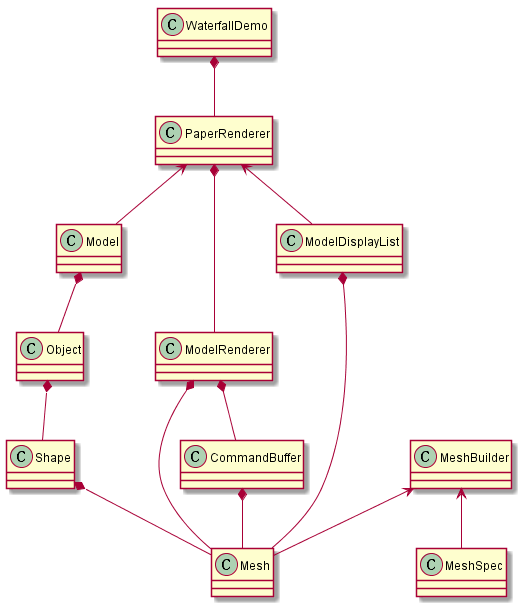
mesh_class_diagram

下面简单介绍一下这些类

Mesh创建过程中,
MeshBuilder根据MeshSpec的设置生成对应的Mesh.
Mesh的vertex/index数据保存到CommandBuffer中,

Mesh渲染过程中,
对应的PageRenderer生成对应的Object,每一个Object都有对应的Mesh,这些Object挂接到Model下面.
然后根据Model中包含的Mesh生成ModelDisplayList,然后遍历这个ModelDisplayList,把Mesh中的vertex/index数据传入CommandBuffer中,从而让GPU渲染的时候能够访问到这些数据.

0x2 各种shape的mesh过程

0x21 MeshBuilder介绍

MeshBuilder提供接口把vertex data和index data保存起来.

其中保存的数据结构如下,
vertex_stagingbuffer保存vertex数据,index_stagingbuffer保存index数据.
vertex_stagingbuffer和index_stagingbuffer的内存空间是通过GpuUploader::Writer来分配的.

1
2
3
4
5
6
7
const size_t max_vertex_count_;
const size_t max_index_count_;
const size_t vertex_stride_;
uint8_t* vertex_staging_buffer_;
uint32_t* index_staging_buffer_;
size_t vertex_count_ = 0;
size_t index_count_ = 0;

下面是其提供设置vertex data和index data的接口.
注意下面的接口都返回 *this, 这是为了链式表达式的需要.

1
2
3
4
5
6
7
8
9
10
11
12
13
14
15
16
17
18
19
inline MeshBuilder& MeshBuilder::AddIndex(uint32_t index) {
FXL_DCHECK(index_count_ < max_index_count_);
index_staging_buffer_[index_count_++] = index;
return *this;
}
inline MeshBuilder& MeshBuilder::AddVertexData(const void* ptr, size_t size) {
FXL_DCHECK(vertex_count_ < max_vertex_count_);
FXL_DCHECK(size <= vertex_stride_);
size_t offset = vertex_stride_ * vertex_count_++;
memcpy(vertex_staging_buffer_ + offset, ptr, size);
return *this;
}
template <typename VertexT>
MeshBuilder& MeshBuilder::AddVertex(const VertexT& v) {
AddVertexData(&v, sizeof(VertexT));
return *this;
}

然后调用Build()接口生成mesh对象.

0x22 SimpleRectangle

下面是生成SimpleRectangle的mesh的代码,SimpleRectangle是普通的非圆角Rectangle.
从这个代码中可以看到,该mesh过程会生成4个vertex数据,生成6个index数据(因为是2个三角形).

1
2
3
4
5
6
7
8
9
10
11
12
13
14
15
16
17
18
19
20
21
22
23
MeshPtr NewSimpleRectangleMesh(MeshBuilderFactory* factory) {
MeshSpec spec{MeshAttribute::kPosition2D | MeshAttribute::kUV};
// In each vertex, the first two floats represent the position and the second
// two are UV coordinates.
vec4 v0(0.f, 0.f, 0.f, 0.f);
vec4 v1(1.f, 0.f, 1.f, 0.f);
vec4 v2(1.f, 1.f, 1.f, 1.f);
vec4 v3(0.f, 1.f, 0.f, 1.f);
MeshBuilderPtr builder = factory->NewMeshBuilder(spec, 4, 6);
return builder->AddVertex(v0)
.AddVertex(v1)
.AddVertex(v2)
.AddVertex(v3)
.AddIndex(0)
.AddIndex(1)
.AddIndex(2)
.AddIndex(0)
.AddIndex(2)
.AddIndex(3)
.Build();
}

前面的mesh过程计算好了一个通用的SimpleRectangle的mesh信息,
具体要显示Rectangle的时候根据具体的显示位置(top_left_position.x/y/z)和显示的大小(size.x/y)来绘制Rectangle.
指定显示的位置可以理解为平移,指定显示的大小可以理解为缩放.
这个平移/缩放过程通过设置transform矩阵来实现,在shader代码中把这个矩阵和通用SimpleRectangle的vertex坐标相乘.

transform矩阵的设置过程如下

1
2
3
4
5
6
7
8
9
10
Object Object::NewRect(const vec3& top_left_position, const vec2& size,
MaterialPtr material) {
mat4 transform(1);
transform[0][0] = size.x;
transform[1][1] = size.y;
transform[3][0] = top_left_position.x;
transform[3][1] = top_left_position.y;
transform[3][2] = top_left_position.z;
return Object(transform, Shape(Shape::Type::kRect), std::move(material));
}

0x23 Rectangle

下面的代码生成普通Rectangle的Mesh,

下面函数的参数中,
subdivisions指定Rectangle的拆分数,
size指定Rectangle的大小,
top_left指定左上角的坐标,
生成mesh的时候把Rectangle分成(subdivisions*2-1)个小矩形,指定这些小矩形的vertex/index设置.

这个普通Rectangle的mesh和SimpleRectangle的mesh不同之处在于普通Rectangle的mesh是每一个Rectangle生成一个,不具有SimpleRectangle的mesh的通用性. 另外普通Rectangle的mesh会包括更多的小三角形.

1
2
3
4
5
6
7
8
9
10
11
12
13
14
15
16
17
18
19
20
21
22
23
24
25
26
27
28
29
30
31
32
33
34
35
36
37
38
39
40
41
42
43
44
45
46
47
48
49
50
51
52
53
54
55
56
57
58
59
60
61
62
MeshPtr NewRectangleMesh(MeshBuilderFactory* factory, const MeshSpec& spec,
int subdivisions, vec2 size, vec2 top_left,
float top_offset_magnitude,
float bottom_offset_magnitude) {
// Compute the number of vertices in the tessellated circle.
FXL_DCHECK(subdivisions >= 0);
size_t vertices_per_side = 2;
while (subdivisions-- > 0) {
vertices_per_side *= 2;
}
size_t vertex_count = vertices_per_side * 2;
size_t index_count = (vertices_per_side - 1) * 6;
auto builder = factory->NewMeshBuilder(spec, vertex_count, index_count);
// Generate vertex positions.
constexpr size_t kMaxVertexSize = 100;
uint8_t vertex[kMaxVertexSize];
auto vertex_p =
GetVertexAttributePointers(vertex, kMaxVertexSize, spec, builder);
FXL_CHECK(vertex_p.pos2);
const float vertices_per_side_reciprocal = 1.f / (vertices_per_side - 1);
for (size_t i = 0; i < vertices_per_side; ++i) {
// Build bottom vertex.
(*vertex_p.pos2) =
top_left + vec2(size.x * i * vertices_per_side_reciprocal, size.y);
if (vertex_p.uv)
(*vertex_p.uv) = vec2(i * vertices_per_side_reciprocal, 1.f);
if (vertex_p.pos_offset)
(*vertex_p.pos_offset) = vec2(0, 1.f * bottom_offset_magnitude);
if (vertex_p.perim)
(*vertex_p.perim) = i * vertices_per_side_reciprocal;
builder->AddVertexData(vertex, builder->vertex_stride());
// Build top vertex.
(*vertex_p.pos2) =
top_left + vec2(size.x * i * vertices_per_side_reciprocal, 0);
if (vertex_p.uv)
(*vertex_p.uv) = vec2(i * vertices_per_side_reciprocal, 0);
if (vertex_p.pos_offset)
(*vertex_p.pos_offset) = vec2(0, -1.f * top_offset_magnitude);
if (vertex_p.perim)
(*vertex_p.perim) = i * vertices_per_side_reciprocal;
builder->AddVertexData(vertex, builder->vertex_stride());
}
// Generate vertex indices.
for (size_t i = 2; i < vertex_count; i += 2) {
builder->AddIndex(i - 2);
builder->AddIndex(i - 1);
builder->AddIndex(i);
builder->AddIndex(i - 1);
builder->AddIndex(i + 1);
}
auto mesh = builder->Build();
FXL_DCHECK(mesh->num_indices() == index_count);
return mesh;
}

0x24 Circle

下面分析circle的mesh是如何生成的.

下面函数的参数中,
subdivisions指定Circle的拆分数目,
center指定Circle的中心点坐标.
radius指定Circle的半径大小.

生成mesh的时候是把Circle分成(subdivisions*4)个小扇形,然后计算这些小扇形的vertex/index设置.

1
2
3
4
5
6
7
8
9
10
11
12
13
14
15
16
17
18
19
20
21
22
23
24
25
26
27
28
29
30
31
32
33
34
35
36
37
38
39
40
41
42
43
44
45
46
47
48
49
50
51
52
53
54
55
56
57
58
59
60
61
62
63
64
65
66
67
68
69
70
71
72
MeshPtr NewCircleMesh(MeshBuilderFactory* factory, const MeshSpec& spec,
int subdivisions, vec2 center, float radius,
float offset_magnitude) {
// Compute the number of vertices in the tessellated circle.
FXL_DCHECK(subdivisions >= 0);
FXL_DCHECK(spec.IsValidOneBufferMesh());
size_t outer_vertex_count = 4;
while (subdivisions-- > 0) {
outer_vertex_count *= 2;
}
size_t vertex_count = outer_vertex_count + 1; // Add 1 for center vertex.
size_t index_count = outer_vertex_count * 3;
auto builder = factory->NewMeshBuilder(spec, vertex_count, index_count);
// Generate vertex positions.
constexpr size_t kMaxVertexSize = 100;
uint8_t vertex[kMaxVertexSize];
auto vertex_p =
GetVertexAttributePointers(vertex, kMaxVertexSize, spec, builder);
// Build center vertex.
FXL_CHECK(vertex_p.pos2);
(*vertex_p.pos2) = center;
if (vertex_p.uv)
(*vertex_p.uv) = vec2(0.5f, 0.5f);
if (vertex_p.pos_offset)
(*vertex_p.pos_offset) = vec2(0.f, 0.f);
// TODO: This is an undesirable singularity. Perhaps it would be better to
// treat circles as a ring with inner radius of zero?
if (vertex_p.perim)
(*vertex_p.perim) = 0.f;
builder->AddVertexData(vertex, builder->vertex_stride());
// Outer vertices.
const float outer_vertex_count_reciprocal = 1.f / outer_vertex_count;
const float radian_step = 2 * M_PI / outer_vertex_count;
for (size_t i = 0; i < outer_vertex_count; ++i) {
float radians = i * radian_step;
// Direction of the current vertex from the center of the circle.
vec2 dir(sin(radians), cos(radians));
(*vertex_p.pos2) = dir * radius + center;
if (vertex_p.uv)
(*vertex_p.uv) = 0.5f * (dir + vec2(1.f, 1.f));
if (vertex_p.pos_offset)
(*vertex_p.pos_offset) = dir * offset_magnitude;
if (vertex_p.perim)
(*vertex_p.perim) = i * outer_vertex_count_reciprocal;
builder->AddVertexData(vertex, builder->vertex_stride());
}
// Vertex indices.
for (size_t i = 1; i < outer_vertex_count; ++i) {
builder->AddIndex(0);
builder->AddIndex(i + 1);
builder->AddIndex(i);
}
builder->AddIndex(0);
builder->AddIndex(1);
builder->AddIndex(outer_vertex_count);
auto mesh = builder->Build();
FXL_DCHECK(mesh->num_indices() == index_count);
FXL_DCHECK(mesh->bounding_box() ==
BoundingBox(vec3(center.x - radius, center.y - radius, 0),
vec3(center.x + radius, center.y + radius, 0)));
return mesh;
}

前面的mesh过程计算好了一个通用的Circle的mesh信息,
和SimpleRectangle的情况类似,具体绘制Circle的时候根据具体的显示位置(center_position.x/y/z)和显示的大小(radius)来绘制Circle.
指定显示的位置可以理解为平移,指定显示的大小可以理解为缩放.
这个平移/缩放过程也是通过设置transform矩阵来实现,在shader代码中把这个矩阵和通用Circle的vertex坐标相乘.

1
2
3
4
5
6
7
8
9
10
Object Object::NewCircle(const vec3& center_position, float radius,
MaterialPtr material) {
mat4 transform(1);
transform[0][0] = radius;
transform[1][1] = radius;
transform[3][0] = center_position.x;
transform[3][1] = center_position.y;
transform[3][2] = center_position.z;
return Object(transform, Shape(Shape::Type::kCircle), std::move(material));
}

0x25 RoundRectangle

下面分析生成圆角Rectangle的mesh的代码.

该过程把圆角矩形mesh成三角形,其中的顶点分布如下图所示,

其中每个圆角部分被拆分成8个小扇形.

RoundedRect

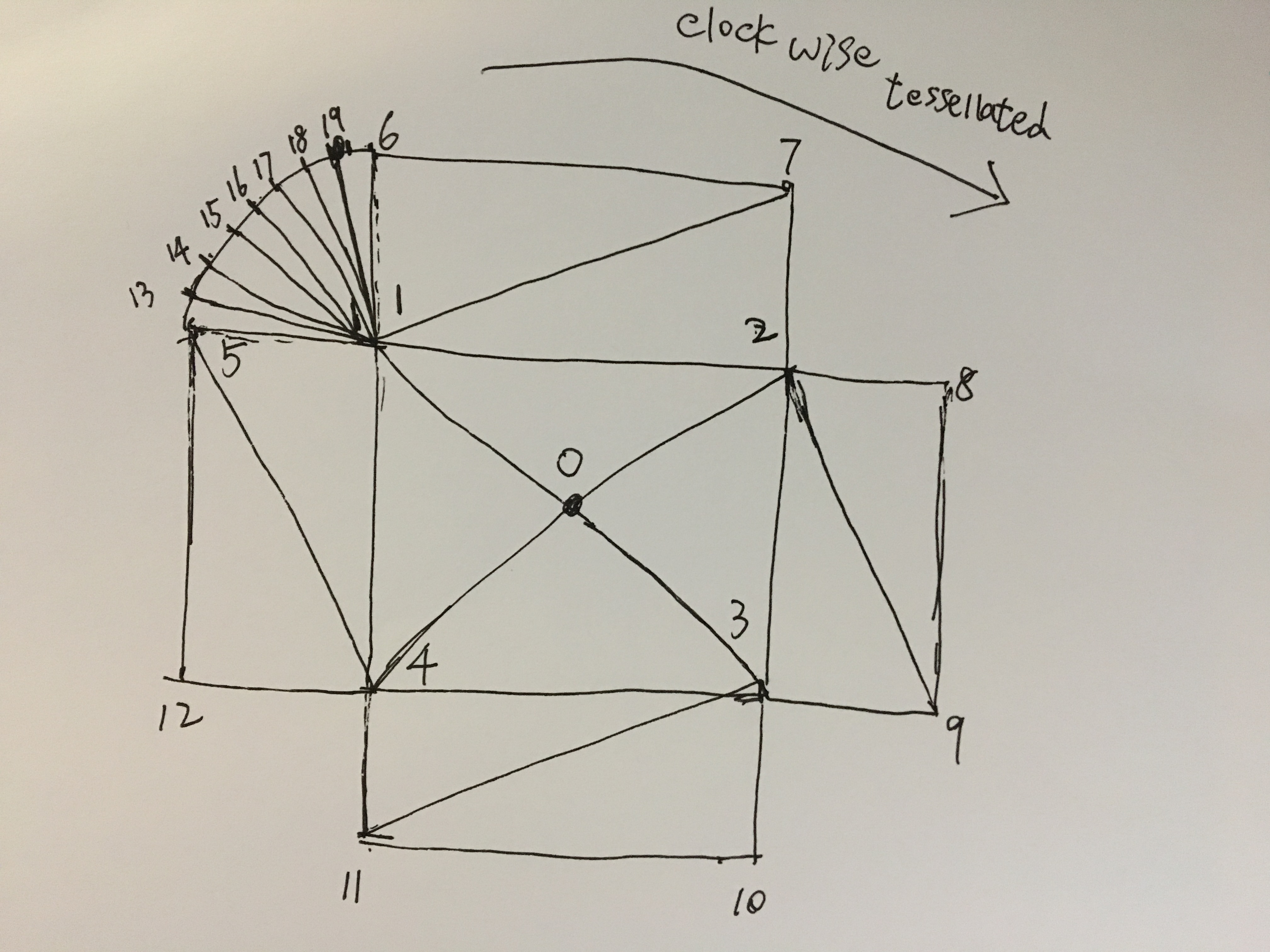
0 ~ 12 顶点是中间部分的矩形对应的顶点.
13 ~ 19 顶点是左上角部分的圆角对应的顶点.
20 ~ 26 顶点是右上角部分的圆角对应的顶点.
27 ~ 33 顶点是右下角部分的圆角对应的顶点.
34 ~ 40 顶点是左下角部分的圆角对应的顶点.

NewRoundedRect是总的入口函数,其中会调用GenerateRoundedRectIndices()来根据顶点来构造三角形,调用GenerateRoundedRectVertexUVs()生成纹理坐标,最后调用GenerateRoundedRectVertexPositionsFromUVs()来生成顶点坐标.

1
2
3
4
5
6
7
8
9
10
11
12
13
14
15
16
17
18
19
20
21
22
23
24
25
26
27
28
29
30
31
32
33
34
35
36
37
38
39
40
41
42
43
44
45
46
47
48
49
50
51
52
53
54
55
56
57
58
59
MeshPtr RoundedRectFactory::NewRoundedRect(
const RoundedRectSpec& spec, const MeshSpec& mesh_spec,
BatchGpuUploader* batch_gpu_uploader) {
FXL_DCHECK(batch_gpu_uploader);
auto index_buffer = GetIndexBuffer(spec, mesh_spec, batch_gpu_uploader);
auto counts = GetRoundedRectMeshVertexAndIndexCounts(spec);
const uint32_t vertex_count = counts.first;
const uint32_t index_count = counts.second;
const size_t primary_buffer_stride = mesh_spec.stride(0);
const size_t secondary_buffer_stride = mesh_spec.stride(1);
const size_t vertex_buffer_size =
vertex_count * (primary_buffer_stride + secondary_buffer_stride);
auto vertex_buffer =
buffer_factory_.NewBuffer(vertex_buffer_size,
vk::BufferUsageFlagBits::eVertexBuffer |
vk::BufferUsageFlagBits::eTransferDst,
vk::MemoryPropertyFlagBits::eDeviceLocal);
const auto bounding_box =
BoundingBox::NewChecked(-0.5f * vec3(spec.width, spec.height, 0),
0.5f * vec3(spec.width, spec.height, 0), 1);
switch (mesh_spec.vertex_buffer_count()) {
case 1: {
auto writer = batch_gpu_uploader->AcquireWriter(vertex_buffer_size);
GenerateRoundedRectVertices(spec, mesh_spec, writer->host_ptr(),
writer->size());
writer->WriteBuffer(vertex_buffer, {0, 0, vertex_buffer->size()});
batch_gpu_uploader->PostWriter(std::move(writer));
return fxl::MakeRefCounted<Mesh>(
static_cast<ResourceRecycler*>(this), mesh_spec, bounding_box,
vertex_count, index_count, vertex_buffer, std::move(index_buffer));
}
case 2: {
auto writer = batch_gpu_uploader->AcquireWriter(vertex_buffer_size);
GenerateRoundedRectVertices(
spec, mesh_spec, writer->host_ptr(),
vertex_count * primary_buffer_stride,
writer->host_ptr() + vertex_count * primary_buffer_stride,
vertex_count * secondary_buffer_stride);
writer->WriteBuffer(vertex_buffer, {0, 0, vertex_buffer->size()});
batch_gpu_uploader->PostWriter(std::move(writer));
return fxl::MakeRefCounted<Mesh>(
static_cast<ResourceRecycler*>(this), mesh_spec, bounding_box,
index_count, std::move(index_buffer), 0, vertex_count, vertex_buffer,
0, std::move(vertex_buffer), vertex_count * primary_buffer_stride);
}
default:
FXL_CHECK(false) << "unsupported vertex buffer count: "
<< mesh_spec.vertex_buffer_count();
return nullptr;
}
}

下面的代码是构造圆角Rectangle中的三角形的过程,indices中保存的是把这些顶点拼接成三角形的顶点索引.

1
2
3
4
5
6
7
8
9
10
11
12
13
14
15
16
17
18
19
20
21
22
23
24
25
26
27
28
29
30
31
32
33
34
35
36
37
38
39
40
41
42
43
44
45
46
47
48
49
50
51
52
53
54
55
56
57
58
59
60
61
62
63
64
65
66
67
68
69
70
71
72
73
74
75
76
77
78
79
80
81
82
83
84
85
86
87
88
89
90
void GenerateRoundedRectIndices(const RoundedRectSpec& spec,
const MeshSpec& mesh_spec, void* indices_out,
uint32_t max_bytes) {
TRACE_DURATION("gfx", "escher::GenerateRoundedRectIndices");
FXL_DCHECK(max_bytes >= kIndexCount * sizeof(uint32_t));
uint32_t* indices = static_cast<uint32_t*>(indices_out);
// Central square triangles.
indices[0] = 0;
indices[1] = 4;
indices[2] = 1;
indices[3] = 0;
indices[4] = 1;
indices[5] = 2;
indices[6] = 0;
indices[7] = 2;
indices[8] = 3;
indices[9] = 0;
indices[10] = 3;
indices[11] = 4;
// "Cross arm 1" triangles.
indices[12] = 1;
indices[13] = 7;
indices[14] = 2;
indices[15] = 1;
indices[16] = 6;
indices[17] = 7;
// "Cross arm 2" triangles.
indices[18] = 2;
indices[19] = 9;
indices[20] = 3;
indices[21] = 2;
indices[22] = 8;
indices[23] = 9;
// "Cross arm 3" triangles.
indices[24] = 3;
indices[25] = 11;
indices[26] = 4;
indices[27] = 3;
indices[28] = 10;
indices[29] = 11;
// "Cross arm 4" triangles.
indices[30] = 4;
indices[31] = 5;
indices[32] = 1;
indices[33] = 4;
indices[34] = 12;
indices[35] = 5;
// WARNING: here's where it gets confusing; the number of indices generated is
// dependent on kCornerDivisions.
// We've already generated output indices for the "cross triangles".
constexpr uint32_t kCrossTriangles = 12;
// Holds the position of the next index to output.
uint32_t out = kCrossTriangles * 3;
// Holds the highest index of any vertex used thus far (the central "cross"
// consists of 13 vertices, whose indices are 0-12).
uint32_t highest_index = 12;
// These are the indices of the 4 triangles that would be output if
// kCornerDivisions were zero.
const uint32_t corner_tris[] = {1, 6, 5, 2, 8, 7, 3, 10, 9, 4, 12, 11};
// For each corner, generate wedges in clockwise order.
for (uint32_t corner = 0; corner < 4; ++corner) {
// Index of the vertex at the center of the current corner.
const uint32_t center = corner_tris[corner * 3];
// As we move clockwise around the corner, this holds the index of the
// previous perimeter vertex.
uint32_t prev = corner_tris[corner * 3 + 2];
for (uint32_t i = 0; i < kCornerDivisions; ++i) {
indices[out++] = center;
indices[out++] = prev;
indices[out++] = prev = ++highest_index;
}
// One last triangle (or the only one, if kCornerDivisions == 0).
indices[out++] = center;
indices[out++] = prev;
indices[out++] = corner_tris[corner * 3 + 1];
}
FXL_DCHECK(out == kIndexCount);
}

下面函数计算这些点(0 ~ 40)对应的纹理(uv)坐标.

1
2
3
4
5
6
7
8
9
10
11
12
13
14
15
16
17
18
19
20
21
22
23
24
25
26
27
28
29
30
31
32
33
34
35
36
37
38
39
40
41
42
43
44
45
46
47
48
49
50
51
52
53
54
55
56
57
58
59
60
61
62
63
64
65
66
67
68
69
70
71
72
73
74
template <typename VertT>
void GenerateRoundedRectVertexUVs(const RoundedRectSpec& spec, VertT* verts) {
TRACE_DURATION("gfx", "escher::GenerateRoundedRectVertexUVs");
const float width = spec.width;
const float height = spec.height;
// First compute UV coordinates of the four "corner centers".
verts[1].uv =
vec2(spec.top_left_radius / width, spec.top_left_radius / height);
verts[2].uv =
vec2(1.f - spec.top_right_radius / width, spec.top_right_radius / height);
verts[3].uv = vec2(1.f - spec.bottom_right_radius / width,
1.f - spec.bottom_right_radius / height);
verts[4].uv = vec2(spec.bottom_left_radius / width,
1.f - spec.bottom_left_radius / height);
// The "center" vertex is the average of the four "corner centers".
verts[0].uv =
0.25f * ((verts[1].uv + verts[2].uv + verts[3].uv + verts[4].uv));
// Next, compute UV coords for the 8 vertices where the rounded corners meet
// the straight side sections.
verts[6].uv = vec2(verts[1].uv.x, 0.f);
verts[7].uv = vec2(verts[2].uv.x, 0.f);
verts[8].uv = vec2(1.f, verts[2].uv.y);
verts[9].uv = vec2(1.f, verts[3].uv.y);
verts[10].uv = vec2(verts[3].uv.x, 1.f);
verts[11].uv = vec2(verts[4].uv.x, 1.f);
verts[12].uv = vec2(0.f, verts[4].uv.y);
verts[5].uv = vec2(0.f, verts[1].uv.y);
// Next, compute UV coords for the vertices that make up the rounded corners.
// We start at index 13; indices 0-12 were computed above.
uint32_t out = 13;
constexpr float kPI = 3.14159265f;
constexpr float kAngleStep = kPI / 2 / (kCornerDivisions + 1);
// Generate UV coordinates for top-left corner.
float angle = kPI + kAngleStep;
vec2 scale =
vec2(spec.top_left_radius / width, spec.top_left_radius / height);
for (size_t i = 0; i < kCornerDivisions; ++i) {
verts[out++].uv = verts[1].uv + vec2(cos(angle), sin(angle)) * scale;
angle += kAngleStep;
}
// Generate UV coordinates for top-right corner.
angle = 1.5f * kPI + kAngleStep;
scale = vec2(spec.top_right_radius / width, spec.top_right_radius / height);
for (size_t i = 0; i < kCornerDivisions; ++i) {
verts[out++].uv = verts[2].uv + vec2(cos(angle), sin(angle)) * scale;
angle += kAngleStep;
}
// Generate UV coordinates for bottom-right corner.
angle = kAngleStep;
scale =
vec2(spec.bottom_right_radius / width, spec.bottom_right_radius / height);
for (size_t i = 0; i < kCornerDivisions; ++i) {
verts[out++].uv = verts[3].uv + vec2(cos(angle), sin(angle)) * scale;
angle += kAngleStep;
}
// Generate UV coordinates for bottom-right corner.
angle = 0.5f * kPI + kAngleStep;
scale =
vec2(spec.bottom_left_radius / width, spec.bottom_left_radius / height);
for (size_t i = 0; i < kCornerDivisions; ++i) {
verts[out++].uv = verts[4].uv + vec2(cos(angle), sin(angle)) * scale;
angle += kAngleStep;
}
}

下面函数计算这些点(0 ~ 40)对应的顶点坐标,根据对应的纹理坐标来计算得到.

1
2
3
4
5
6
7
8
9
10
11
12
13
// Helper for GenerateRoundedRectVertices().
template <typename UvVertT, typename PosVertT>
void GenerateRoundedRectVertexPositionsFromUVs(const RoundedRectSpec& spec,
UvVertT* uv_verts,
PosVertT* pos_verts) {
TRACE_DURATION("gfx", "escher::GenerateRoundedRectVertexPositionsFromUVs");
const vec2 extent(spec.width, spec.height);
const vec2 offset = -0.5f * extent;
for (size_t i = 0; i < kVertexCount; ++i) {
pos_verts[i].pos = uv_verts[i].uv * extent + offset;
}
}

0x26 Sphere

下面是构造Sphere的mesh的代码.

1
2
3
4
5
6
7
8
9
10
11
12
13
14
15
16
17
18
19
20
21
22
23
24
25
26
27
28
29
30
31
32
33
34
35
36
37
38
39
40
41
42
43
44
45
46
47
48
49
50
51
52
53
54
55
56
57
58
59
60
61
62
63
64
65
66
67
68
69
70
71
72
73
74
75
76
77
78
79
80
81
82
83
84
85
86
87
88
89
90
91
92
93
94
95
96
97
98
99
100
101
102
MeshPtr NewSphereMesh(MeshBuilderFactory* factory, const MeshSpec& spec,
int subdivisions, vec3 center, float radius) {
FXL_DCHECK(subdivisions >= 0);
FXL_DCHECK(spec.IsValidOneBufferMesh());
size_t vertex_count = 9;
size_t triangle_count = 8;
for (int i = 0; i < subdivisions; ++i) {
// At each level of subdivision, an additional vertex is added for each
// triangle, and each triangle is split into three.
vertex_count += triangle_count;
triangle_count *= 3;
}
// Populate initial octahedron.
auto builder =
factory->NewMeshBuilder(spec, vertex_count, triangle_count * 3);
constexpr size_t kMaxVertexSize = 100;
uint8_t vertex[kMaxVertexSize];
auto vertex_p =
GetVertexAttributePointers(vertex, kMaxVertexSize, spec, builder);
FXL_CHECK(vertex_p.pos3);
// Positions and UV-coordinates for the initial octahedron. The vertex with
// position (-radius, 0, 0) is replicated 4 times, with different UV-coords
// each time. This is a consequence of surface parameterization that is
// described in the header file.
const vec3 positions[] = {vec3(radius, 0.f, 0.f), vec3(0.f, 0.f, radius),
vec3(0.f, -radius, 0.f), vec3(0.f, 0.f, -radius),
vec3(0.f, radius, 0.f), vec3(-radius, 0.f, 0.f),
vec3(-radius, 0.f, 0.f), vec3(-radius, 0.f, 0.f),
vec3(-radius, 0.f, 0.f)};
const vec2 uv_coords[] = {vec2(.5f, .5f), vec2(1.f, .5f), vec2(.5f, 0.f),
vec2(0.f, .5f), vec2(.5f, 1.f), vec2(0.f, 0.f),
vec2(1.f, 0.f), vec2(1.f, 1.f), vec2(0.f, 1.f)};
for (int i = 0; i < 9; ++i) {
(*vertex_p.pos3) = positions[i] + center;
if (vertex_p.uv) {
(*vertex_p.uv) = uv_coords[i];
}
builder->AddVertexData(vertex, builder->vertex_stride());
}
builder->AddTriangle(0, 1, 2)
.AddTriangle(0, 2, 3)
.AddTriangle(0, 3, 4)
.AddTriangle(0, 4, 1)
.AddTriangle(5, 2, 1)
.AddTriangle(6, 3, 2)
.AddTriangle(7, 4, 3)
.AddTriangle(8, 1, 4);
// TODO(ES-32): this is a hack to ease implementation. We don't currently
// need any tessellated spheres; this is just a way to verify that 3D meshes
// are working properly.
FXL_DCHECK(spec.attributes[0] ==
(MeshAttribute::kPosition3D | MeshAttribute::kUV))
<< "Tessellated sphere must have UV-coordinates.";
size_t position_offset = reinterpret_cast<uint8_t*>(vertex_p.pos3) - vertex;
size_t uv_offset = reinterpret_cast<uint8_t*>(vertex_p.uv) - vertex;
while (subdivisions-- > 0) {
// For each level of subdivision, iterate over all existing triangles and
// split them into three.
// TODO(ES-32): see comment in header file... this approach is broken, but
// sufficient for our current purpose.
const size_t subdiv_triangle_count = builder->index_count() / 3;
FXL_DCHECK(subdiv_triangle_count * 3 == builder->index_count());
for (size_t tri_ind = 0; tri_ind < subdiv_triangle_count; ++tri_ind) {
// Obtain indices for the current triangle, and the position/UV coords for
// the corresponding vertices.
uint32_t* tri = builder->GetIndex(tri_ind * 3);
uint32_t ind0 = tri[0];
uint32_t ind1 = tri[1];
uint32_t ind2 = tri[2];
uint8_t* vert0 = builder->GetVertex(ind0);
uint8_t* vert1 = builder->GetVertex(ind1);
uint8_t* vert2 = builder->GetVertex(ind2);
vec3 pos0 = *reinterpret_cast<vec3*>(vert0 + position_offset);
vec3 pos1 = *reinterpret_cast<vec3*>(vert1 + position_offset);
vec3 pos2 = *reinterpret_cast<vec3*>(vert2 + position_offset);
vec2 uv0 = *reinterpret_cast<vec2*>(vert0 + uv_offset);
vec2 uv1 = *reinterpret_cast<vec2*>(vert1 + uv_offset);
vec2 uv2 = *reinterpret_cast<vec2*>(vert2 + uv_offset);
// Create a new vertex by averaging the existing vertex attributes.
(*vertex_p.pos3) =
center + radius * glm::normalize((pos0 + pos1 + pos2) / 3.f - center);
(*vertex_p.uv) = (uv0 + uv1 + uv2) / 3.f;
builder->AddVertexData(vertex, builder->vertex_stride());
// Replace the current triangle in-place with a new triangle that refers
// to the new vertex. Then, add two new triangles that also refer to the
// new vertex.
uint32_t new_ind = builder->vertex_count() - 1;
tri[2] = new_ind;
builder->AddTriangle(ind1, ind2, new_ind)
.AddTriangle(ind2, ind0, new_ind);
}
}
return builder->Build();
}

0x27 Ring

下面分析Ring的mesh是如何生成的, Ring是由内圈和外圈包含的区域组成, 内圈区域内是透明的, 实际上Ring的mesh没有包括内圈,也就是说渲染的时候不会去绘制内圈区域, 所以mesh生成的绘制区域只需要包括内圈和外圈组成的区域,mesh的过程也就是把内圈和外圈之间的区域拆分成许多小三角形.

下面函数的参数中,
subdivisions指定Ring的拆分数.
center指定Circle的中心点坐标.
outer_radius指定Ring的外圈半径.
inner_radius指定Ring的内圈半径.

生成mesh的时候把Ring分成(subdivisions*4)个小扇形,这些小扇形会和Ring的内圈和外圈相交,
指定相交点的vertex值,然后把这些vertex组成的triangle,vertex的index值指定给mesh的index.

1
2
3
4
5
6
7
8
9
10
11
12
13
14
15
16
17
18
19
20
21
22
23
24
25
26
27
28
29
30
31
32
33
34
35
36
37
38
39
40
41
42
43
44
45
46
47
48
49
50
51
52
53
54
55
56
57
58
59
60
61
62
63
64
65
66
67
68
69
70
71
72
73
74
75
76
77
78
79
80
81
82
83
84
MeshPtr NewRingMesh(MeshBuilderFactory* factory, const MeshSpec& spec,
int subdivisions, vec2 center, float outer_radius,
float inner_radius, float outer_offset_magnitude,
float inner_offset_magnitude) {
// Compute the number of vertices in the tessellated circle.
FXL_DCHECK(subdivisions >= 0);
FXL_DCHECK(spec.IsValidOneBufferMesh());
size_t outer_vertex_count = 4;
while (subdivisions-- > 0) {
outer_vertex_count *= 2;
}
size_t vertex_count = outer_vertex_count * 2;
size_t index_count = outer_vertex_count * 6;
auto builder = factory->NewMeshBuilder(spec, vertex_count, index_count);
// Generate vertex positions.
constexpr size_t kMaxVertexSize = 100;
uint8_t vertex[kMaxVertexSize];
auto vertex_p =
GetVertexAttributePointers(vertex, kMaxVertexSize, spec, builder);
FXL_CHECK(vertex_p.pos2);
const float outer_vertex_count_reciprocal = 1.f / outer_vertex_count;
const float radian_step = 2 * M_PI / outer_vertex_count;
for (size_t i = 0; i < outer_vertex_count; ++i) {
float radians = i * radian_step;
// Direction of the current vertex from the center of the circle.
vec2 dir(sin(radians), cos(radians));
// Build outer-ring vertex.
(*vertex_p.pos2) = dir * outer_radius + center;
if (vertex_p.uv) {
// Munge the texcoords slightly to avoid wrapping artifacts. This matters
// when both:
// - the vk::SamplerAddressMode is eRepeat
// - the vk::Filter is eLinear
(*vertex_p.uv) = 0.49f * (dir + vec2(1.f, 1.02f));
// TODO(ES-108): once we can specify a SamplerAddressMode of eClampToEdge,
// remove the hack above and replace it with the code below:
// (*vertex_p.uv) = 0.5f * (dir + vec2(1.f, 1.f));
}
if (vertex_p.pos_offset)
(*vertex_p.pos_offset) = dir * outer_offset_magnitude;
if (vertex_p.perim)
(*vertex_p.perim) = i * outer_vertex_count_reciprocal;
builder->AddVertexData(vertex, builder->vertex_stride());
// Build inner-ring vertex. Only the position and offset may differ from
// the corresponding outer-ring vertex.
(*vertex_p.pos2) = dir * inner_radius + center;
if (vertex_p.pos_offset) {
// Positive offsets point inward, toward the center of the circle.
(*vertex_p.pos_offset) = dir * -inner_offset_magnitude;
}
builder->AddVertexData(vertex, builder->vertex_stride());
}
// Generate vertex indices.
for (size_t i = 2; i < vertex_count; i += 2) {
builder->AddIndex(i - 2);
builder->AddIndex(i - 1);
builder->AddIndex(i);
builder->AddIndex(i - 1);
builder->AddIndex(i + 1);
}
builder->AddIndex(vertex_count - 2);
builder->AddIndex(vertex_count - 1);
builder->AddIndex(0);
builder->AddIndex(vertex_count - 1);
builder->AddIndex(1);
auto mesh = builder->Build();
FXL_DCHECK(mesh->num_indices() == index_count);
FXL_DCHECK(
mesh->bounding_box() ==
BoundingBox(vec3(center.x - outer_radius, center.y - outer_radius, 0),
vec3(center.x + outer_radius, center.y + outer_radius, 0)));
return mesh;
}