

Mixed Render Architecture
0x1 混合渲染架构
在开发渲染程序的过程中,我们常常会碰到需要把多个渲染引擎混合在一起使用的场景,如android中渲染视频数据的时候还需要渲染UI。游戏中渲染游戏3D场景的时候还需要渲染UI等场景。本文对这种混合渲染的架构进行了总结。下面对五种混合渲染方式进行了分别介绍。
0x2 SurfaceView

我们知道SurfaceView是在Android中提出的概念。Android中的UI显示采用了View的架构进行处理,View可以满足大部分的绘图需求,但是有时候,View却显得力不从心,所以Android提供了SurfaceView给Android开发者,以满足更多的绘图需求。
SurfaceView是一个组件,可用于在View层次结构中嵌入其他合成层。但因为SurfaceView拥有独立于主View之外的独立渲染线程,SurfaceView的内容对其他View来说是透明的,也就是说SurfaceView的绘制游离于其他View的控制之外。
使用SurfaceView进行渲染时,SurfaceFlinger会直接将SurfaceView的输出缓冲区直接合成到屏幕上。如果没有SurfaceView,则需要将绘制内容先绘制到其他View对应的Surface中,注意该Surface也包括了其他View的内容绘制,然后再作为一层合成到屏幕上,而使用SurfaceView进行渲染可以省去额外的工作。但是SurfaceView是作为单独的一层合成到屏幕上的,在拥有绘制灵活性的同时也消耗了更多的内存。
View和SurfaceView的区别主要有这两点,
一是View适用于主动更新的情况,而SurfaceView则适用于被动更新的情况,比如频繁刷新界面。另外一点是View是在主线程中对页面进行刷新,而SurfaceView则需要开启一个子线程来对页面进行刷新。
GLSurfaceView
GLSurfaceView提供了帮助管理EGL上下文、在线程间通信以及与activity生命周期交互的辅助程序类。GLSurfaceView会创建一个渲染线程,并在线程上配置EGL上下文。大多数应用无需了解有关 EGL 的任何信息即可通过 GLSurfaceView 来使用GLES。
0x3 TextureView
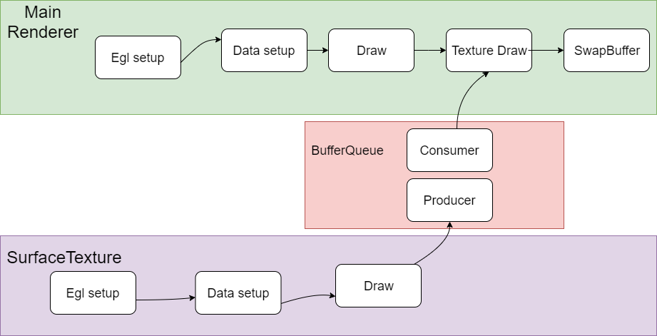
TextureView一般和SurfaceTexture配合使用。
SurfaceTexture一般包括producer和consumer模块,producer负责生产texture,生产好了通知consumer,consumer把texture作为view的贴图输入完成SurfaceTexture的绘制。TextureView 类是一个结合了 View 和 SurfaceTexture 的 View 对象。可以理解为在主窗口的体系之内的子View,和主窗口的其他View形成父子关系,可以一起联动,形成复杂的渲染效果。
SurfaceTexture 是Surface和OpenGL ES (GLES)纹理的组合。SurfaceTexture实例用于提供输出到 GLES 纹理的接口。
SurfaceTexture包含一个以应用为使用方的BufferQueue实例。当生产方将新的缓冲区排入队列时,onFrameAvailable() 回调会通知应用。然后,应用调用updateTexImage()。这会释放先前占用的缓冲区,从队列中获取新缓冲区并执行EGL调用,从而使GLES可将此缓冲区作为外部纹理使用。
TextureView对象会对SurfaceTexture进行包装,从而响应回调以及获取新的缓冲区。在TextureView获取新的缓冲区时,TextureView会发出View失效请求,并使用最新缓冲区的内容作为数据源进行绘图,根据View状态的指示,以相应的方式在相应的位置进行呈现。
与SurfaceView 相比,TextureView具有更出色的UI绘制操作能力,但在视频上以分层方式合成界面元素时,SurfaceView具有性能方面的优势。当客户端使用SurfaceView呈现内容时,SurfaceView会为客户端提供单独的合成层。如果设备支持,SurfaceFlinger会将单独的层合成为硬件叠加层。当客户端使用TextureView呈现内容时,界面工具包会使用GPU将 TextureView的内容合成到视图层次结构中。对内容进行的更新可能会导致其他View元素重绘,例如,在其他View被置于TextureView顶部时。View呈现完成后,SurfaceFlinger会合成应用界面层和所有其他层,以便每个可见像素合成两次。
0x4 同一个Context 直接渲染
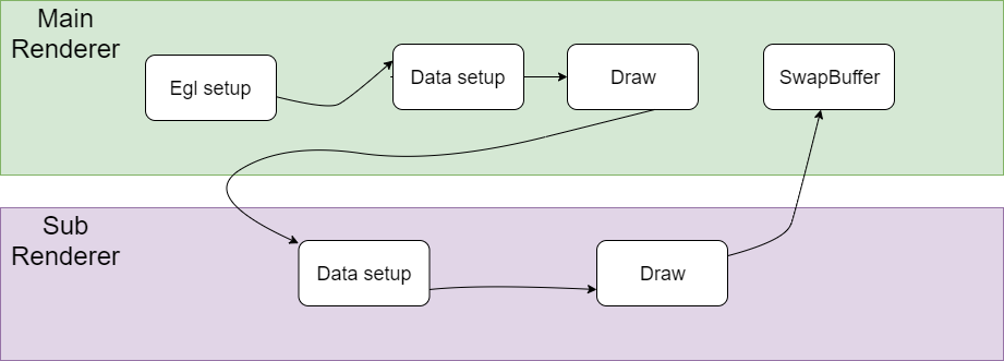
我们把这种渲染混合方式叫做DirectRender。
简单把流程说明如下,这里假设渲染采用EGL与系统窗口系统进行对接。
Main Render负责创建EGL环境,然后CPU准备绘制数据,并把绘制数据送到GPU,然后调用GPU Draw函数进行绘制,注意这个时候并没有调用SwapBuffer,
而是去调用了Sub Render的绘制流程,在SubRender中同样完成绘制数据准备和调用GPU Draw函数进行绘制的过程,最后再去调用SwapBuffer。
在Main Render和Sub Render的切换过程中,涉及到GL状态的切换,可能两个Render之间的设置存在冲突,需要有一个保存和恢复的过程,另外有些状态的设置需要在两个引擎之间配合好,否则会出现各种显示问题。
另外一点是这个Main Render和Sub Render是在同一个渲染线程中运行,没有多线程的切换。
0x5 同一个Context fbo渲染
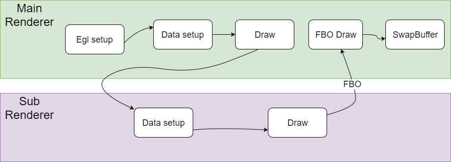
简单把流程说明如下,
Main Render负责创建EGL环境,然后CPU准备绘制数据,并把绘制数据送到GPU,然后调用GPU Draw函数进行绘制,
然后调用了Sub Render的绘制流程,Sub Render的绘制结果是保存在framebuffer object中,这个framebuffer object和一个texture绑定在一起。
在SubRender中同样完成绘制数据准备和调用GPU Draw函数进行绘制以后,也就是说对framebuffer object进行了写入,这个时候texture也就准备好了,
Main Render拿着这个texture作为输入,再进行一次绘制,最后再去调用SwapBuffer输出。
在Main Render和Sub Render的切换过程中,也涉及到GL状态的切换,有些状态的设置也是需要在两个引擎之间配合好,否则会出现各种显示问题。另外一点是这个Main Render和Sub Render也是在同一个渲染线程中运行。
0x6 Shared context渲染
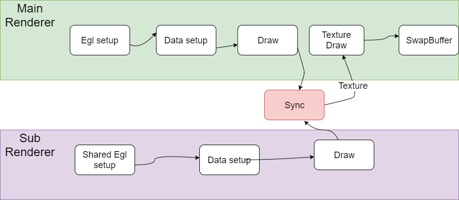
简单把流程说明如下,
Main Render负责创建EGL环境,然后CPU准备绘制数据,并把绘制数据送到GPU,然后调用GPU Draw函数进行绘制。
Sub Render通过shared context的方式创建,也是需要完成EGL设置的过程,另外这个Sub Render创建的Surface是Pbuffer,是offscreen的。
另外这个Sub Render的绘制结果也是保存在framebuffer object中,这个framebuffer object和一个texture绑定在一起。
在SubRender中同样完成绘制数据准备和调用GPU Draw函数进行绘制以后,这个时候Main Render和Sub Render有一个sync的操作。
保证对Sub Render对framebuffer object进行了写入,texture也是准备好了。
然后Main Render拿着这个texture作为输入,再进行一次绘制,最后再去调用SwapBuffer输出。
在Main Render和Sub Render的切换过程中,由于采用的是Shared Context架构,GL状态在Main Render和Sub Render之间相对比较独立,相互的影响比较小。另外一点是这个Main Render和Sub Render是在两个独立的渲染线程中运行。
下面再对Shared Context的绘制渲染架构进行详细的分析。
我们知道OpenGL是一个线程级别的状态机,其操作被局限在一个线程中进行。OpenGL 的绘制命令都是作用在当前的 Context 上,这个 Current Context是一个线程私有thread-local)的变量。如果在多线程环境下操作同一个opengl context,对opengl api的调用需要加锁进行保护。否则会出现各种问题。
通过共享context架构,上下文是可以在多个线程间共享的,在使用eglCreateContext时, 可以传入一个已创建成功的上下文, 这样就可以得到一个共享的上下文(Shared Context),我们可以实现多个渲染线程并行处理,其中一些线程作为生产者,这些生产者一般是离屏渲染,生成相关纹理供另外的线程消费、
举例来说, Google为Android的MediaCodec设计了一套基于OpenGL的Pipeline, 其涉及的模块包括 Video Capture, Pre-processing, Encode, Decode, Post processing,Render等。上述的整个Pipeline会在多个线程中工作. 可以使用Shared Context的方式为这个架构设计高度优化的Pipeline,这样设计思路也比较自然。如果强制设计为单独context的架构,各个线程的OpenGL操作都需要post任务到OpenGL线程来处理,涉及到多次加锁保护的过程,无论是架构的可读性,还是系统的性能应该都会受到影响。
另外Shared Context架构下共享资源有纹理,shader,Buffer等。不共享资源有FBO, VAO等。
0x7 Shared Contxt架构下纹理共享访问问题
这个问题是Shared Contxt架构下渲染绘制crash问题,场景是webview播放视频的时候crash,crash的位置在GPU驱动中,但是具体原因未知。
大概的渲染流程是这样的,UI渲染是Main Render负责的,webview播放视频是Sub Render绘制完成的,其中用到了Shared context架构,webview播放视频的过程渲染到纹理中,Main Render拿到这个纹理后完成真正的视频内容绘制。
通过分析大概的渲染流程,我怀疑是Shared context架构下纹理访问冲突问题。根据前面的分析,Sub Render会通过填充纹理内容的方式生产绘制内容,Main Render得到纹理内容以后再读入GPU,最后完成渲染。如果Main Render读取纹理内容的同时,Sub Render正在填充纹理的话,肯定就发生访问冲突了。
我们通过一个单元测试来模拟这个问题。看看出现crash的地方是否和真实场景下出错的地方一致。
piglit下面有相关的Shared Context测试,代码位于piglit/tests/glx/glx-multithread-texture.c
其中包括一个纹理填充线程,一个纹理读取线程。我们通过在修改测试代码,模拟前面说的读取个填充纹理同时发生的情况。
但是很遗憾,没有出现crash。看来这个问题对timing很敏感,应该是特定时序下发生的问题
看来这能在GPU驱动代码mesa中hack来复现了。如下所示,这个是在Main Render执行纹理读取设置的时候加一个sleep等待。等待Sub Render有足够的时间去修改纹理设置。果然这样hack以后问题必现,而且出错的堆栈和真实场景下完全一致。
这样问题基本定位,最后发送确实是webview里面播放视频的时候分配的buffer不够用,导致Main Render和Sub Render出现纹理访问冲突的问题。
|
|
0x8 参考资料
https://source.android.google.cn/devices/graphics/arch-st?hl=zh-cn
https://zhuanlan.zhihu.com/p/444440326
Linux Memory Management


Thread Model of Unreal Engine
0x1 数据组织
Unreal Engine的数据组织是典型的Scene Graph数据结构。
Scene拥有Component。
Component是各种渲染节点的抽象。
Render通过访问Scene拥有的Component来完成各种渲染操作。
0x2 线程模型
Unreal Engine代码中封装了典型的Thread/Looper机制来支持多线程。
多线程之间的通信采用Post Task的方式来进行,避免了加锁操作。
下图说明了Unreal Engine三个线程之间的交互。
Unreal Engine的三个线程分别是GameThread, RenderThread, RHIThread。
GameThread可以理解为Controller线程,完成整个渲染流程的控制。
RenderThread是典型的渲染流程,从Scene中读入数据,完成各种效果的处理,然后调用RHIThread完成绘制。
RHIThread是具体调用图形API(OpenGL, DirectX, Vulkan, Metal)来完成绘制的线程。
下图说明了Unreal Engine绘制的简要流程。
下图说明了Unreal Engine渲染模块的层次调用关系。
Slate是Unreal Engine中包括的UI渲染框架。
Renderer里面包括两种渲染器。
然后是RenderCore模块。包括各种渲染效果的处理。
最底层是具体调用图形API的调用。
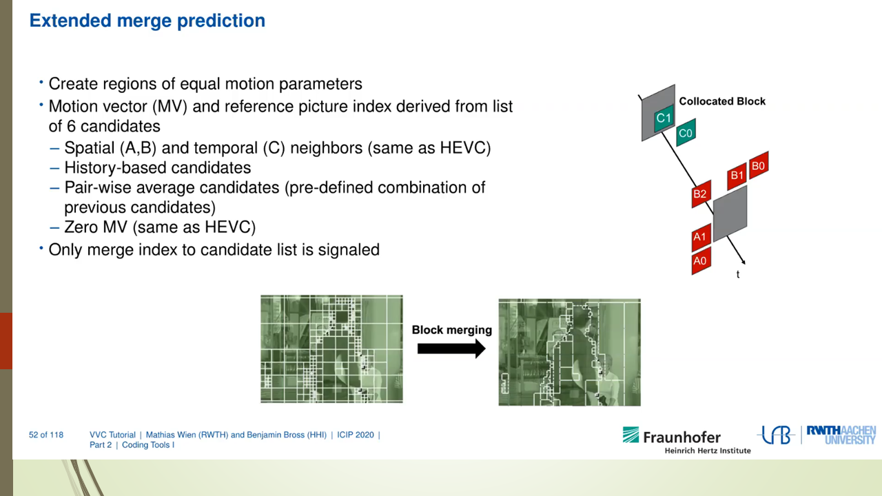
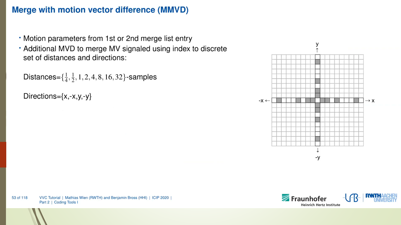
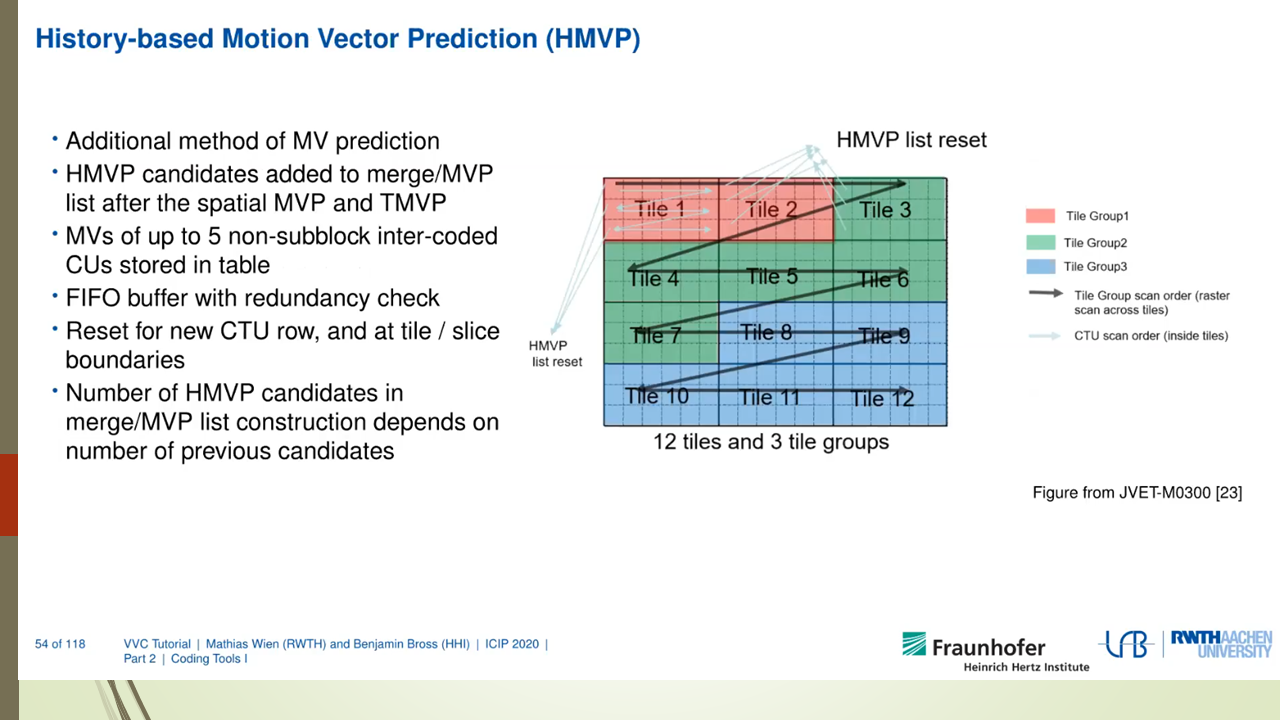
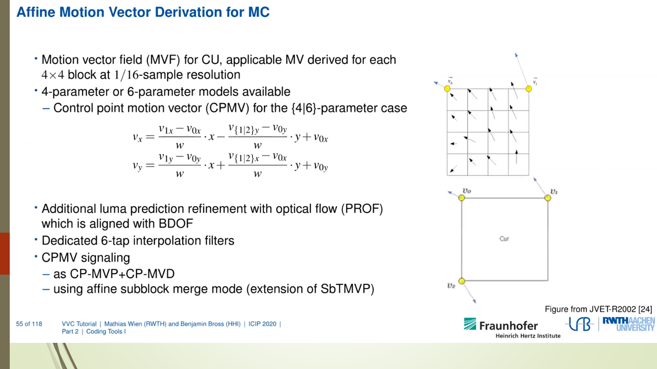
VVC Decoder Analysis
1. 目前VVC Codec现状
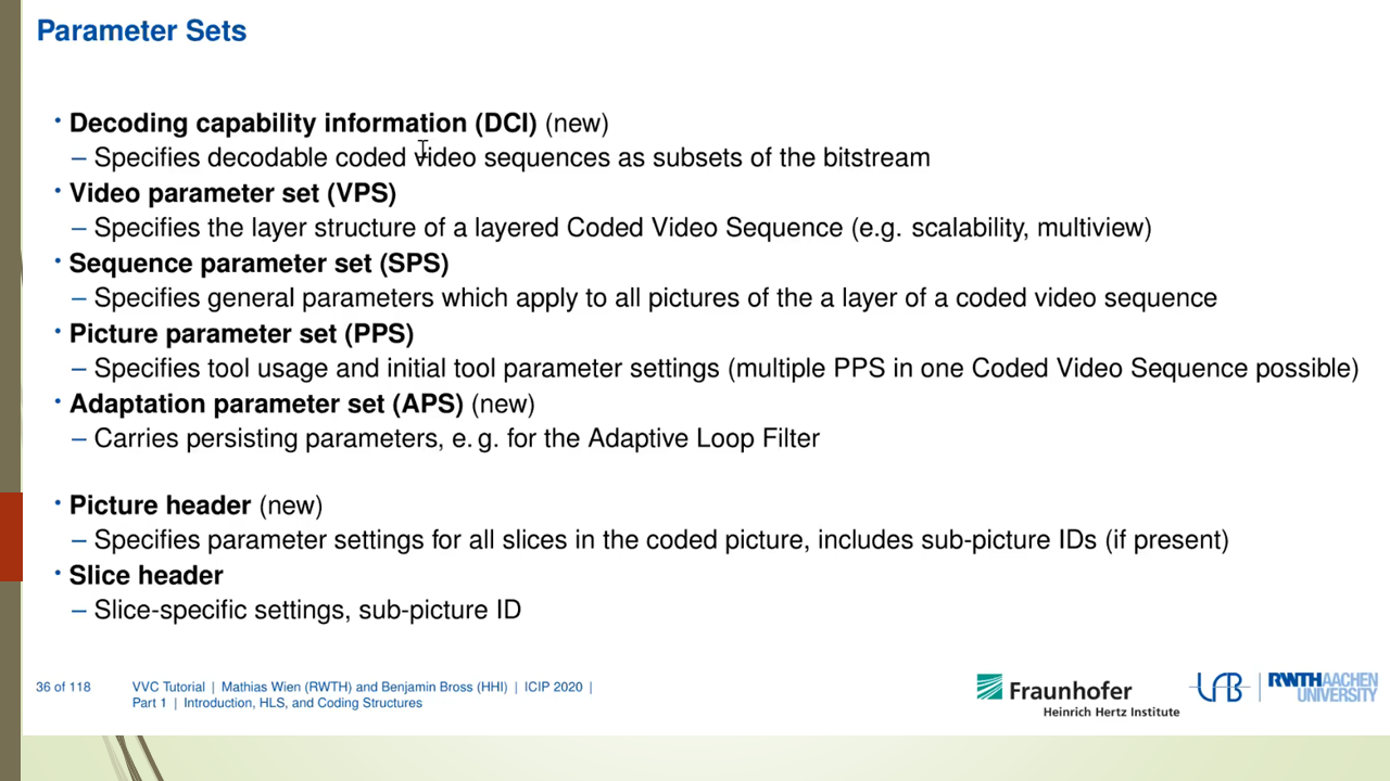
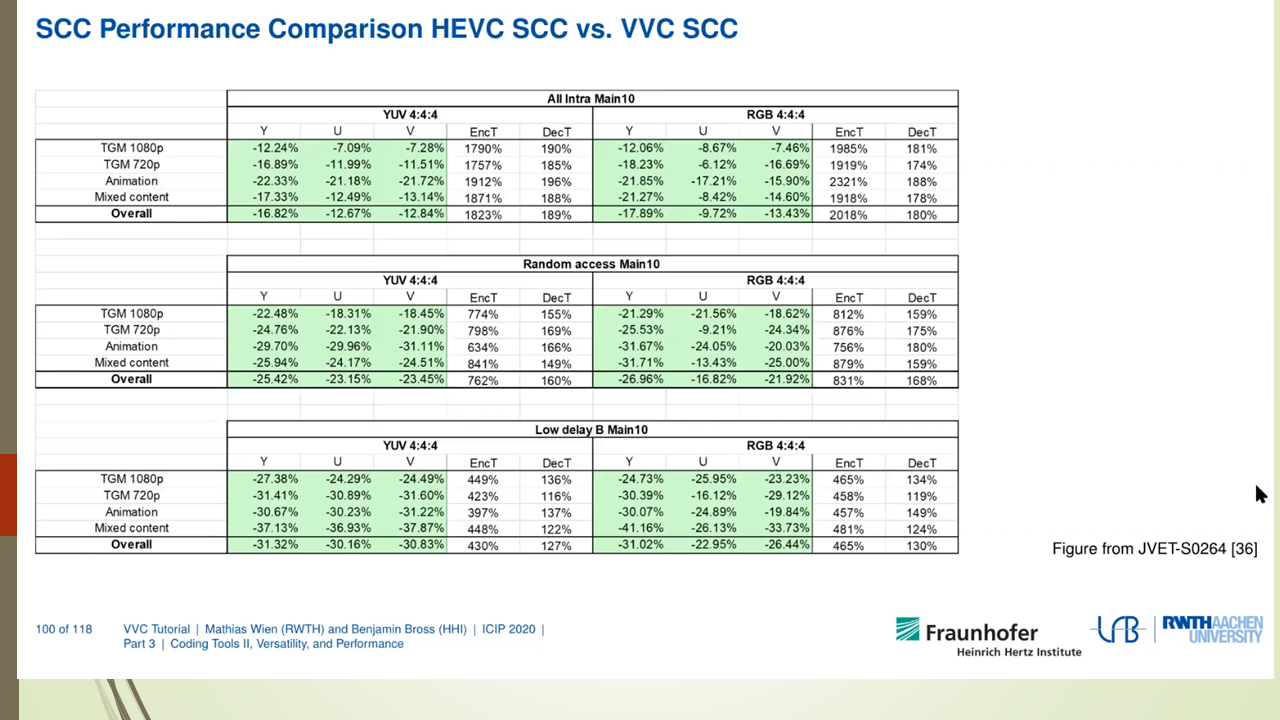
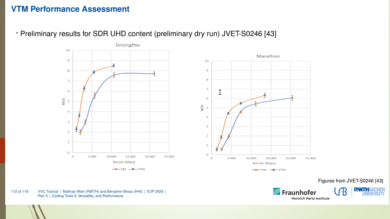
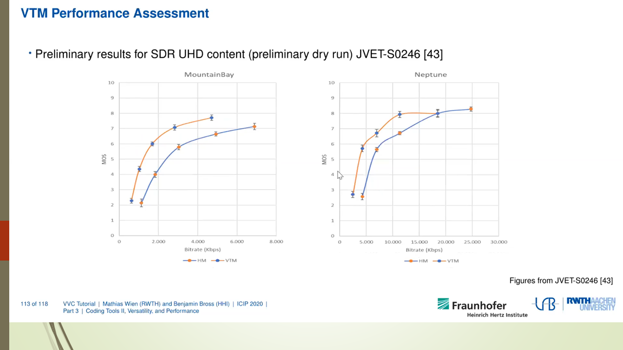
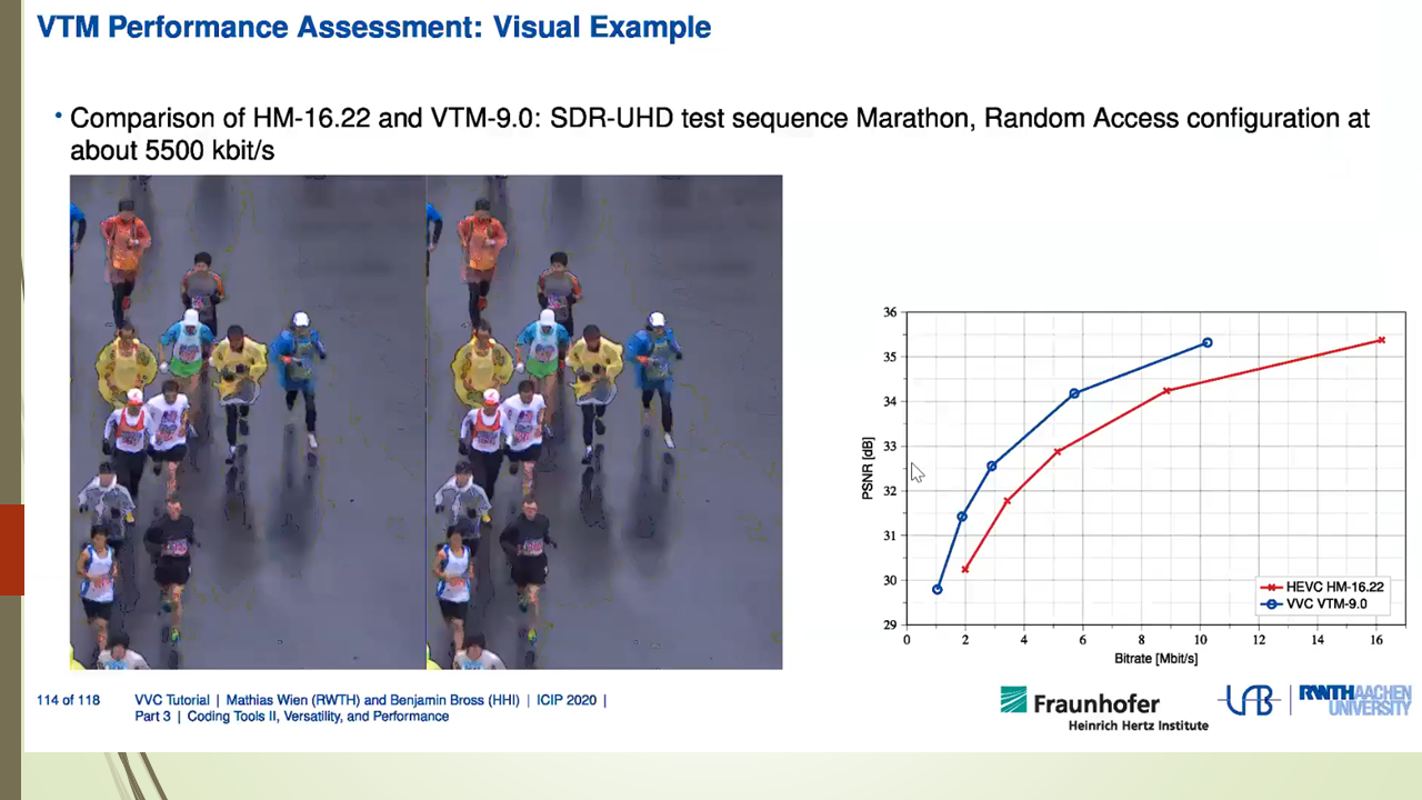
VVC标准已经于2020年正式成为国际标准,我们很想知道到目前为至VVC codec在产业界和学术界的实现情况是怎样的呢?
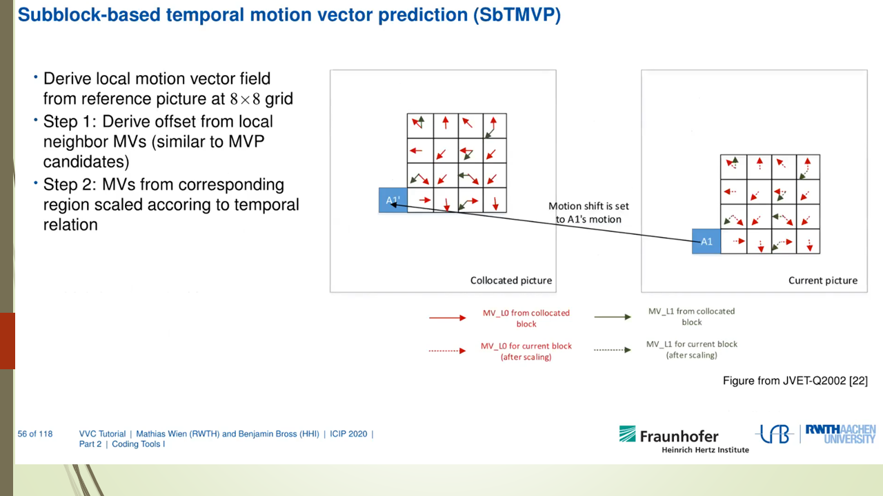
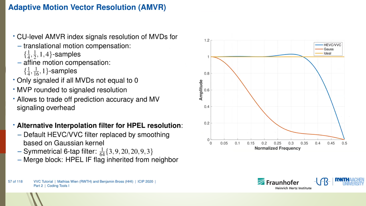
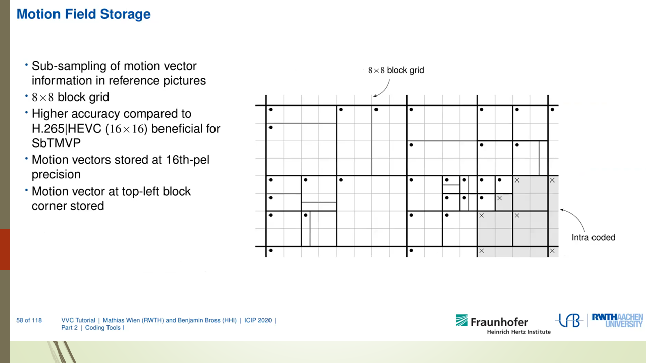
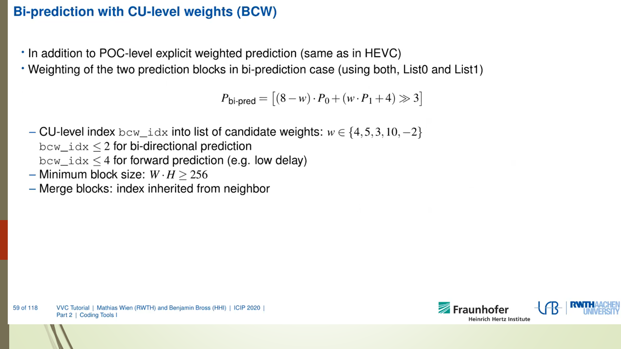
最新的JVET-V0021文档列举了VVC标准的最新实现进展。下面选取了JVET-V0021文档中对这部分的总结介绍, 更详细的信息请参考该文档。
1.1 Publicly available software source code
1) JVET has developed the VVC Test Model (VTM) as its reference software encoder and decoder codebase [5]. It is intended primarily to demonstrate coding efficiency capability and proper interpretation of the syntax and decoding process specified in the standard (but not as a speed-optimized implementation), and is intended to be usable as a starting basis for product implementations. The software is available under a BSD copyright licence.
2) InterDigital developed a multi-threaded VTM decoder, and reported 6–10× speed-up relative to the single-threaded reference software [6]. It is intended to support all features of the VTM. The software was later placed in an accessible repository, and it is available under the same BSD copyright licence as the VTM software [7].
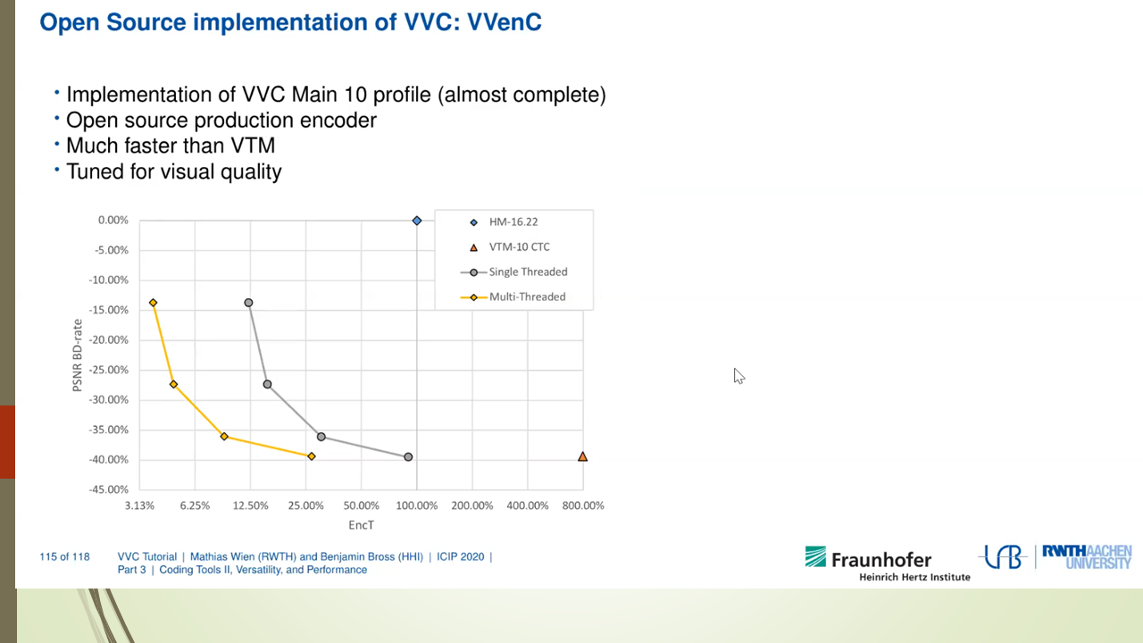
3) Fraunhofer HHI announced the VVenC encoder and VVdeC decoder open-source software (release 0.1) in September 2020 [8][9][10][11][12]. It includes support for multithreading operation, single-pass rate control, perceptual QP adaptation, and motion-compensated temporal filtering (MCTF). The software has four defined presets for quality/speed tradeoff (called “slow”, “medium”, “fast”, and “faster”). Subjective testing reported in October 2020 indicated that the VVenC encoder had about the same or better subjective compression performance as the VTM encoder when operating in its “medium” speed configuration (operating with MCTF and QP adaptation disabled in the VTM and enabled in VVenC and with rate control disabled in both) with encoding speed more than 100× that of the VTM, for 4K UHD SDR video content [12][13]. As of December 2020, a “slower” preset was added, along with an improved single-pass rate control and a new two-pass rate control [14]. The “slower” preset mode reportedly achieves approximately the same BD-rate coding efficiency as the VTM while providing a speedup of more than 8.6x for UHD and 5.2x for HD sequences relative to the VTM. As of December 2020, with release 0.2, the software is available under a BSD copyright licence. Release 0.3 of March 2021 includes substantial further speed and multithreading improvements [15].
4) Friedrich–Alexander University Erlangen–Nürnberg released an open-source bitstream analyser as an add-on for the VTM decoder [16][17]. The analyzer counts the occurrence of coding tools and coding modes used in a decoded bitstream and can be used for evaluating the decoding energy and time demands of VVC features. The software is available under a BSD copyright licence.
1.2 Software decoders
1) Sharp announced a real-time software decoder in June 2020, and issued a corresponding press release in December 2020 [18][19]. As of June 2020, it was reportedly capable of decoding 4K CTC UHD bitstreams at up to 40 Mbps at more than 60 fps.
2) Tencent announced its O266dec software decoder with SIMD and multithreading support and an associated FFmpeg/VLC-based video player in October 2020 [12][20][21]. As of December 2020, it is reportedly more than 3× the speed of the VTM reference software decoder when tested under VVC common test conditions (CTC) in single-threaded operation and about 20× the VTM decoder speed in 8-thread operation. It could reportedly decode UHD video at more than 60 fps at up to 40 Mbps and decode full HD video at more than 200 fps. In December 2020, a version with mobile platform support based on Arm Neon technology was reported. On an Apple A14 processor (iPhone 12pro) in single-threaded operation, it could reportedly decode 8-bit 1080p CTC bitstreams at more than 50 fps, and in multi-threaded operation it could decode such bitstreams at more than 100 fps and could decode 8-bit 4K UHD bitstreams at more than 30 fps in the RA configuration [22]. Although 8-bit operation was more optimized, the decoder also supports 10-bit operation.
3) Alibaba announced its Ali266 decoder for mobile devices (e.g., Android and iPhone) in December 2020 [23]. It includes optimizations for multi-threading, ARM assembly, cache efficiency, and memory usage, particularly for 8 bit video content. Real-time speed is reported for 8 bit 720p, 1080p (using 2–4 threads for up to 60 fps) and 4K (up to 7 Mbps) video content with the ALF feature disabled.
1.3 Bitstream analyser products
1) Elecard announced support for VVC in its StreamEye and StreamAnalyzer products in April 2020 [24].
2) ViCueSoft supports VVC in its VQ Analyzer bitstream analysis product, as of late 2020 [25].
1.4 Conformance test sets
1) A conformance test set is under development by JVET. It reached the CD stage of the ISO/IEC approval process in October 2020 [26].
2) Allegro DVT began offering a conformance test set for VVC as early as January 2020 (i.e., initially in preliminary form before the finalization of the standard) [27][28][29].
1.5 Encoding products and services
1) KDDI Research announced a real-time VVC encoder with 4K @60 fps capability in September 2020 [30].
2) Ateme launched support for VVC in its Titan family of products, and demonstrated the technology in an OTT channel launched in November 2020 [31].
3) Bitmovin, in partnership with Fraunhofer HHI based on VVencC as described in item 3, announced support of VVC in its video encoding platform in November 2020 [32].
2. VVDec流程介绍
VVDec是Fraunhofer HHI开发的VVC解码器,实现了VVC解码器和进一步的优化,包括多线程优化和x86 SIMD优化。本文后面部分重点介绍一下VVDec中有关多线程解码的部分。
2.1 解码流程介绍
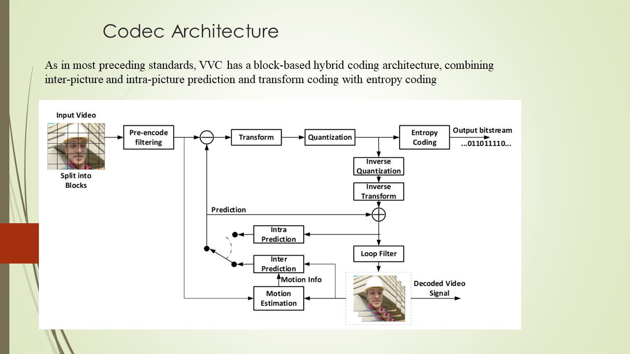
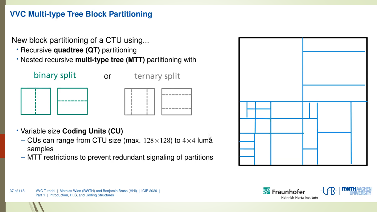
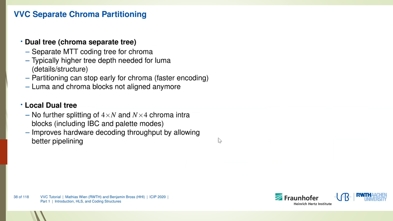
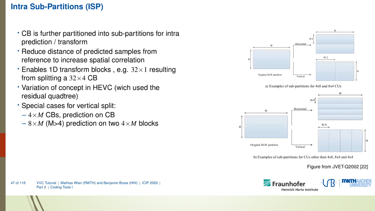
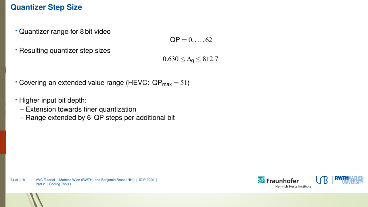
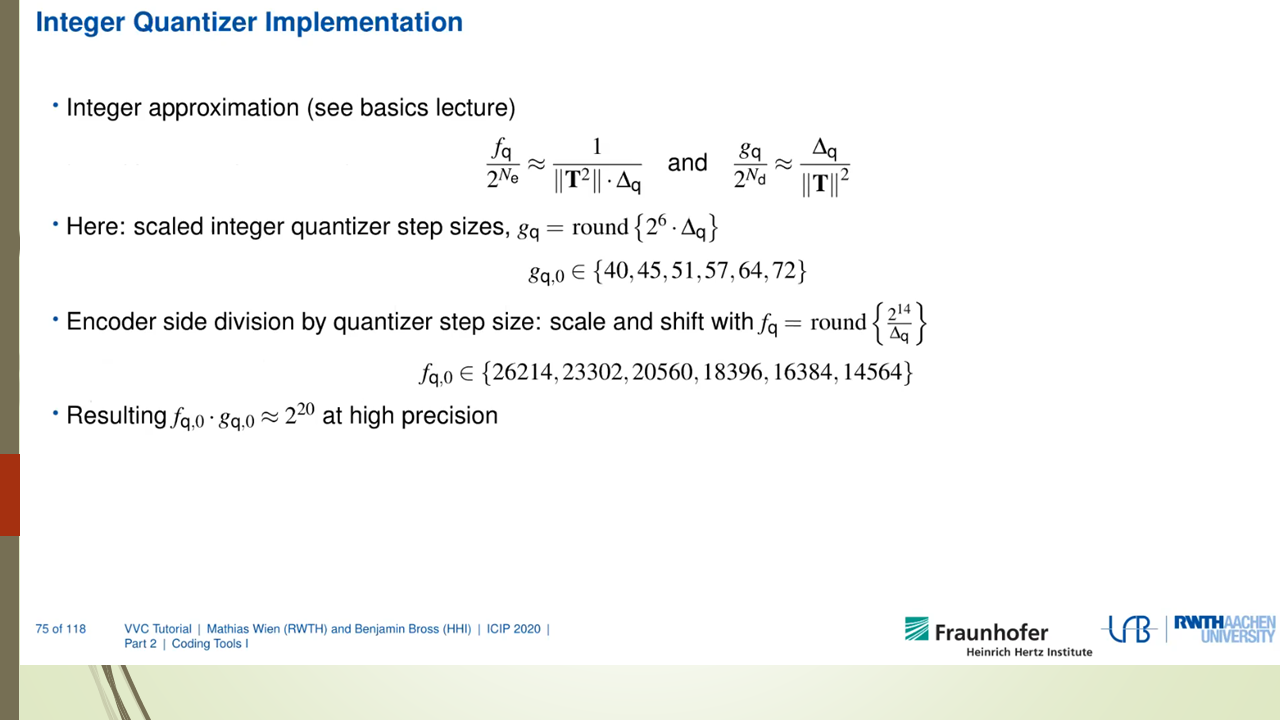
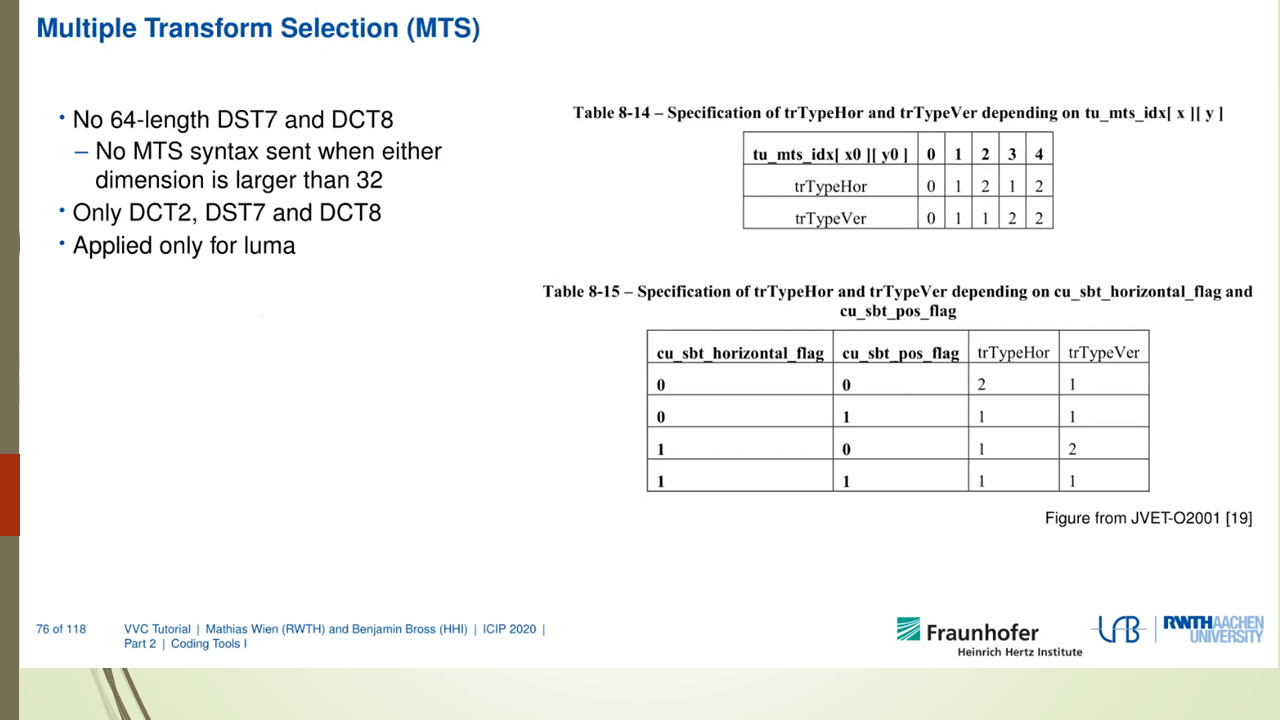
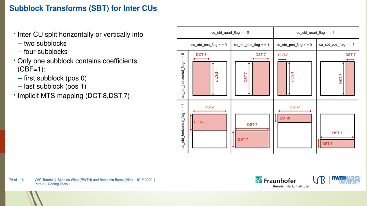
VVC codec标准也是采用了传统的编解码器框架,由帧内预测,帧间预测,变换编码,量化,熵编码,环内滤波等子算法组成。VVC能提升编码压缩率的原因是对上述的子算法都进行了fine tuned,采用了复杂度更高,计算量更大的方法来提高压缩率。
VVC decoder的解码过程也是和传统的video decoder框架一致。首先是parser阶段,采用熵解码对基本的语法元素进行解码,然后是反量化过程,反量化的结果作为变换解码的输入,变换解码输出为残差值。这个残差值和解码得到的预测值相加就得到了解码数据。预测值解码数据又分成帧内预测解码和帧间预测解码两种,分别从时间域和空间域得到相应的预测数据。解码数据最后还需要进行滤波处理才能作为最后的解码输出和帧间预测解码的输入数据。
2.2 CTU粒度多线程解码
我们知道video decoder的并行处理方式有GOP并行,frame并行,slice并行等。这些并行处理方式的实现相对简单,也是比较通用,不同的codec可以采取类似的机制来实现,如ffmpeg就把frame并行和slice并行做成了简单的框架,然后各个codec再调用这个通用的框架来实现并行处理。前面说的并行处理的缺点是并行处理的任务分配可能不均匀,不能很好地利用目前CPU多核的架构来进行充分地codec优化。VVdec实现的是另外一种并行处理机制。该机制把一帧图片的解码分别分成几部分并行执行,每个部分对应一个CTU行或者几个CTU行。我们把这个并行出来任务称为CTU task。这种并行处理方式粒度更小,更能充分利用多核的能力。
CTU task的划分如下图所示。
每个CTU task的解码过程再分成下面这些子任务。
1234
enum TaskType{ /*TRAFO=-1,*/ MIDER, LF_INIT, INTER, INTRA, RSP, LF_V, LF_H, PRESAO, SAO, ALF, DONE, DMVR};
每个子任务开始之前都需要检查当前子任务的依赖是否已经执行完。如果依赖已经完成,则继续往下执行。如果依赖没有完成,则把该任务重新放入线程池中等待下次调度。在任务执行的每个阶段开始执行的时候都需要判断当前阶段对应的依赖有没有完成,如果没有,则退出当前任务执行,把任务重新放入线程池中等待下次调度。这个过程如下图所示。
下面来看一下这些子任务的依赖分别是什么。首先把图片划分成多个ctu task, 每个ctu task包括若干个ctu。每个ctu task是一个线程执行任务的最小单位。每个ctu task都有一个对应的TaskType来表示当前task对应解码状态,也就是说表示当前解码进行到哪一步了。这样我们可以通过比较依赖ctutask的TaskType来判断当前ctu task的依赖条件是否满足。
INTER的依赖
数组thisLine和lineAbove分别表示当前ctu task行和上一个ctu task行的子任务状态。下面的代码表示当前ctu task需要等待123456789101112if( std::all_of( cs.picture->slices.begin(), cs.picture->slices.end(), []( const Slice* pcSlice ) { return pcSlice->isIntra(); } ) ){// not really necessary, but only for optimizing the wave-frontsif( col > 1 && thisLine[col - 2] <= INTER )return false;if( line > 0 && lineAbove[col] <= INTER )return false;}if( std::any_of( cs.picture->refPicExtDepBarriers.cbegin(), cs.picture->refPicExtDepBarriers.cend(), []( const Barrier* b ) { return b->isBlocked(); } ) ){return false;}INTRA的依赖
数组thisLine和lineAbove分别表示当前ctu task行和上一个ctu task行的子任务状态。下面的代码表示当前ctu task需要等待左边和右上的ctu task执行完成INTRA子任务才能开始执行(好像漏了正上方ctu task的判断?后续需要进一步确认)。1234if( col > 0 && thisLine[col - 1] <= INTRA )return false;if( line > 0 && lineAbove[std::min( col + 1, widthInCtus - 1 )] <= INTRA )return false;LF_V的依赖
垂直滤波需要等待左边ctu task完成了INTRA才能开始。12if( col > 0 && thisLine[col - 1] < LF_V )return false;LF_H的依赖
水平滤波需要等待右边,上边和右上的ctu task完成了垂直滤波才能开始。123456if( line > 0 && lineAbove[col] < LF_H )return false;if( line > 0 && col + 1 < widthInCtus && lineAbove[col + 1] < LF_H )return false;if( col + 1 < widthInCtus && thisLine[col + 1] < LF_H )return false;
2.3 ThreadPool的设计
为了实现CTU task的并行,vvdec中设计了一个ThreadPool来完成线程的调度和执行。这个ThreadPool初始化的时候创建N个执行线程,N通常设置为通过std::thread::hardware_concurrency()得到的CPU核数。为了完成无锁化设计,这个线程池提供了类似Fence的机制Barrier来保证前后task之间的依赖关系。也就是说一个task被push到线程池中来执行的时候,其带有特定的Barrier,这个Barrier就是该task执行之前需要保证的条件。
ThreadPool的定义如下所示。
下面来简单介绍一下这个类的定义。
- ChunkedTaskQueue是用来保存task的队列。每个task的定义保存在结构体Slot中。task的func是需要真正执行任务的回调函数。readyCheck是task任务执行之前用来判断是否前置条件是否ready的回调函数。barriers也是task执行之前需要满足的前置条件。也就是说task可以被执行的前置条件是readyCheck回调函数需要返回true,加上barriers不能是block的。1234567891011using TaskFunc = bool ( * )( int, void * );struct Slot{TaskFunc func { nullptr };TaskFunc readyCheck{ nullptr };void* param { nullptr };WaitCounter* counter { nullptr };Barrier* done { nullptr };CBarrierVec barriers;std::atomic<TaskState> state { FREE };};
ChunkedTaskQueue的定义如下。
先定义了一个包含128的Slot结构体数组的Chunk来保存task。在定义一个指向Chunk的单链表来把更多的task任务链接到一起。
完整的ThreadPool接口定义如下。
|
|
其中的核心函数定义如下。
addBarrierTask()提供接口把外部任务push到ThreadPool中来异步执行。
threadProc()是每个线程的loop执行函数,每个线程创建好了以后,threadProc就会在一个while循环中不停地从queue中取出task(如果有的话)来执行。如果queue里面没有task需要执行了,threadProc会进入等待状态。
findNextTask()用于从queue找到一个可以被执行的task。其会调用checkTaskReady()函数用来确保task可以被执行。
checkTaskReady()函数用于检查Barrier和readCheck是否已经准备好。
processTask()用来调用task的执行回调函数执行真正的任务。如果任务没有执行完成(返回false),则该task会重新送入queue中等待下一步再被调用到来执行回调函数。
下面这个图详细说明了ctu解码过程中是如何利用thread pool进行task的调度的。
DecLibRecon把ctu task push到threadpool中的queue中,这些task都带有前置条件。
threadpool中的线程启动loop函数threadProc, threadProc会去queue中取task。如果取得的task的前置条件都满足,则该thread可以去执行对应的task。在执行的过程中某一个子任务完成后会去更新task type。并判断下一步的子任务是否可以启动,如果不行的话该线程退出执行任务,并把任务重新push到queue中,如果可以下一步的子任务可以启动则继续往下执行直至该任务完全结束。
3 参考
Apple M1 GPU分析
0x1 介绍
随着Apple M1 Soc的问世,大家对其集成的GPU也是充满了好奇,根据专业软件的评测,该GPU的性能也是相当强悍。
但是秉承Apple封闭的特性,人们很难直接对其有更深入的了解。但是这个阻挡不了hacker借助各种手段来对其进行逆向分析。
本文就是对目前Apple M1 GPU的逆向分析进展的一个总结。
我们知道Mesa是Linux上开源的图形驱动,支持了Intel,AMD,Broadcom VideoCore,Qualcomm Adreno, ARM Mali, Vivante等厂家的GPU驱动,对了,好像被你看出来了少了谁,这就是Imagination GPU,是的Imagination内部支持Mesa的工程师跳槽到Intel以后,mesa中Imagination GPU的支持就一直没有进展。
Mesa开发模式简单说来有两种,一种是企业支持的开发,如Intel Open source center是Mesa最大的贡献者,开发了Mesa框架,编译器,Intel Gen GPU驱动等。Broadcom也支持了内部工程师来开发Mesa中有关VideoCore GPU的驱动。采用这种模式开发的话可以访问该公司内部完整的技术文档,包括GPU spec,GPU ISA document等。这种开发模式基本是follow对应closed source的GPU驱动流程,根据内部的GPU参考代码,在Mesa中做移植,没有涉及到逆向工程的概念。
另外一种是独立开发模式,这种主要通过逆向工程来分析GPU的特征。这种模式开发的驱动,一看这个取名就很有意思,freedreno,etnaviv,lima,一看就是野路子,就是把人家的名字反过来叫。采用这种模式开发的GPU驱动是在没有参考代码对GPU的特性做逆向分析,然后归纳总结出QPU驱动的流程来,需要完成GPU ISA的总结,开发GPU ISA编译器后端,开发GPU command stream的构造器。使其可以对接到kernel驱动中。采用这种模式开发可以参考的是GPU kernel driver的代码,因为Linux kernel driver代码一般是GPL协议的,可以在网上找到对应的源代码。下面要说的Apple M1 GPU就是通过这种方式开发的。通过了解这个过程,我们可以知道怎样通过逆向分析来完成一个GPU用户态驱动的开发。
这个逆向分析过程由Alyssa Rosenzweig提供,Alyssa Rosenzweig因为负责Mesa中Mali GPU(Panfrost)驱动的逆向开发工作而获得了2021年度的杰出自由软件贡献者奖。
其开发过程如下。
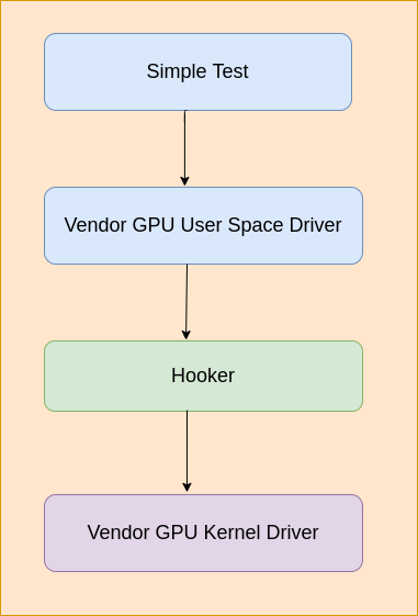
开发Linux or Android逆向GPU驱动的过程如下。
写一个hook库,该hook库用来hook ioctl和mmap接口,然后通过LD_PRELOAD加载进测试程序中,然后在hook的ioctl和mmap函数中分析GPU用户态发送到
内核态的内容,一旦“submit command buffer”被触发,就把内存中的内容dump到文件中,可以用来做进一步分析。
Apple系统上逆向过程如下。
M1 GPU的逆向分析过程也和上面的过程类似,只是macOS上没有LD_PRELOAD,只有类似的机制DYLD_INSERT_LIBRARIES,另外ioctl也是没有的,需要用
macOS上的IOKit framework来代替。IOKit framework是macOS上GPU用户态驱动到内核态驱动的桥梁,其中和ioctl类似的入口函数是IOConnectCallMethod。
下面来详细介绍一下这个逆向过程
提供对IOKit中函数IOConnectCallMethod的包装,也就是说对IOKit进行了hook。
重点关注下面三处调用。memory allocation, command buffer creation, and command buffer submission
把上面的hook接好了以后,就可以利用上面的hook机制来分析驱动了。下面说了这个标准过程,就是利用一个简单的Metal测试程序,
然后在hook中dump驱动的二进制输出,然后对Metal测试程序做一个小修改,然后dump驱动的二进制输出,并和修改前的dump输出进行比较,从而推断出某一个二进制GPU指令对应的含义。通过上面的分析,可以得出M1 GPU的大概特性。
123456789101112131415161718192021222324One, the architecture is scalar. Unlike some GPUs that are scalar for 32-bits but vectorized for 16-bits,the M1’s GPU is scalar at all bit sizes. Yet Metal optimization resources imply 16-bit arithmeticshould be significantly faster, in addition to a reduction of register usage leading to higher threadcount (occupancy). This suggests the hardware is superscalar, with more 16-bit ALUs than 32-bit ALUs,allowing the part to benefit from low-precision graphics shaders much more than competing chips can,while removing a great deal of complexity from the compiler.Two, the architecture seems to handle scheduling in hardware, common among desktop GPUs but less so in the embedded space.This again makes the compiler simpler at the expense of more hardware. Instructions seem to have minimal encodingoverhead, unlike other architectures which need to pad out instructions with nop’s to accommodate highly constrainedinstruction sets.Three, various modifiers are supported. Floating-point ALUs can do clamps (saturate), negates, and absolute valuemodifiers “for free”, a common shader architecture trait. Further, most (all?) instructions can type-convertbetween 16-bit and 32-bit “for free” on both the destination and the sources, which allows the compilerto be much more aggressive about using 16-bit operations without risking conversion overheads.On the integer side, various bitwise complements and shifts are allowed on certain instructions for free.None of this is unique to Apple’s design, but it’s worth noting all the same.Finally, not all ALU instructions have the same timing. Instructions like imad, used to multiply two integers andadd a third, are avoided in favour of repeated iadd integer addition instructions where possible.This also suggests a superscalar architecture; software-scheduled designs like those I work on for my dayjob cannot exploit differences in pipeline length, inadvertently slowing down simple instructions to matchthe speed of complex ones.分析command stream的构建过程,完成以后,我们可以编写一个简单的测试程序跑起来。
0x2 GPU驱动分析
下面来介绍一下这个通过逆向分析得到的GPU驱动。
0x21 wrap
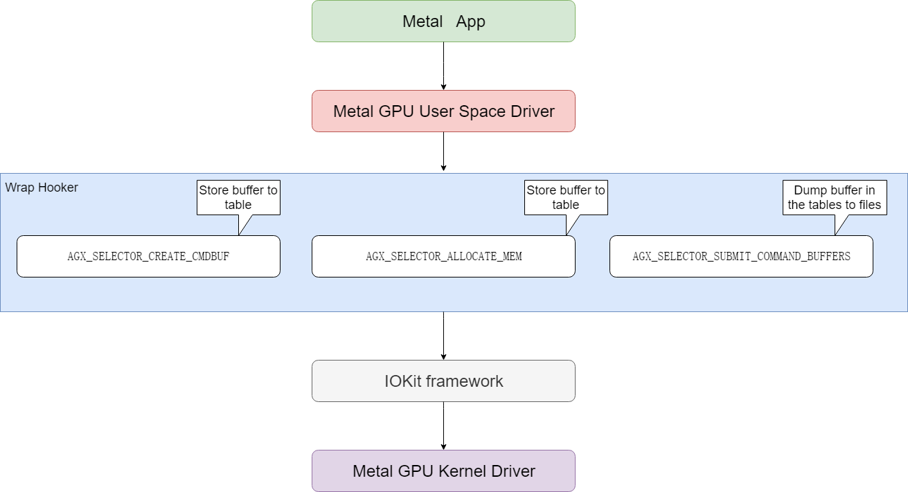
wrap模块定义了下面hook导出函数供应用程序调用,用来接管IOKit中对应的函数。
|
|
然后在图形测试程序运行的时候,会先调用到wrap实现的hook函数中,然后在hook中内存分配(AGX_SELECTOR_ALLOCATE_MEM)和cmd buffer创建(AGX_SELECTOR_CREATE_CMDBUF)被调用的时候记录相应的buffer内存地址,在command命令提交的时候(AGX_SELECTOR_SUBMIT_COMMAND_BUFFERS)把前面保存的buffer保存到文件中。hook函数在完成前述的hook任务以后,再调用真正的IOKit函数,完成对MacOS系统GPU kernel驱动的调用。
0x22 disasm
前面已经把所有包含GPU渲染命令的buffer都保存到文件了,下一步就是要分析这些文件了,这个时候需要disasm发挥作用了。
我们知道M1 GPU是没有公开的文档,开发disasm也是需要反复修改测试程序,然后通过wrap收集到修改后测试程序的命令。通过仔细比较差异来推测这些buffer里面对应的二进制的含义。目前disasm只是对部分GPU ISA进行了解析,对command stream部分的解析没有完成。
目前已经分析出来的部分GPU ISA的opcode如下所示。
|
|
0x23 demo
demo是hack一个简单的测试程序,来驱动M1 GPU kernel driver完成绘制工作。我们前面的wrap有点类似record的意思,这个demo是把record的东西playback出来,playback的输入有些是直接从record的buffer中得到的,有些是通过分析已经大概知道了命令的格式,可以自由地配置出来。
demo启动后首先要通过open类似的接口IOServiceOpen()打开GPU kernel驱动,然后就可以往kernel driver发送内容了。
发送渲染内容到kernel driver的完整代码如下。
|
|
上述过程简单说明如下。
a. 通过AGX_SELECTOR_CREATE_COMMAND_QUEUE创建command queue。
b. 通过AGX_SELECTOR_ALLOCATE_MEM分配buffer,包括AGX_MEMORY_TYPE_FRAMEBUFFER,AGX_MEMORY_TYPE_SHADER,AGX_MEMORY_TYPE_CMDBUF_32等类型的buffer。
c. 通过AGX_SELECTOR_CREATE_CMDBUF分配cmd buffer。
d. 下面开始往前面分配的buffer中填充具体的渲染数据了。这些渲染数据有的是前面通过wrap方式保存下来的,有的是分析后知道格式后自己配置的。这些渲染数据包括shader数据,其中包括了GPU指令,另外就是command stream控制命令。
e. 数据都准备好了,下面就是可以调用AGX_SELECTOR_SUBMIT_COMMAND_BUFFERS提交到GPU执行了。
f. 等等GPU执行完成以后,就可以把framebuffer中的内容读取出来了,直接读取framebuffer.map地址所对应的内容即可,需要注意的是framebuffer里面的内容是tile格式的,需要完成到raster格式的转换才能正确地显示出来。
0x3 总结
目前的驱动基本上是record + playback + kernel的模式,对Shader source code -> GPU ISA的生成和Command Stream的动态配置没有涉及到。其实是为后续通过逆向分析来开发GPU ISA和Command Stream的动态生成提供了框架。后续的开发工作可以在这个框架的基础上继续开发。
0x4 参考
asahi-gpu-part-1
asahi-gpu-part-2
free-software-awards-winners
AsahiLinux GPU
Apple GPU M1 ISA
IOKit参考
Neural network coding tool in VVC
0x1 VVC
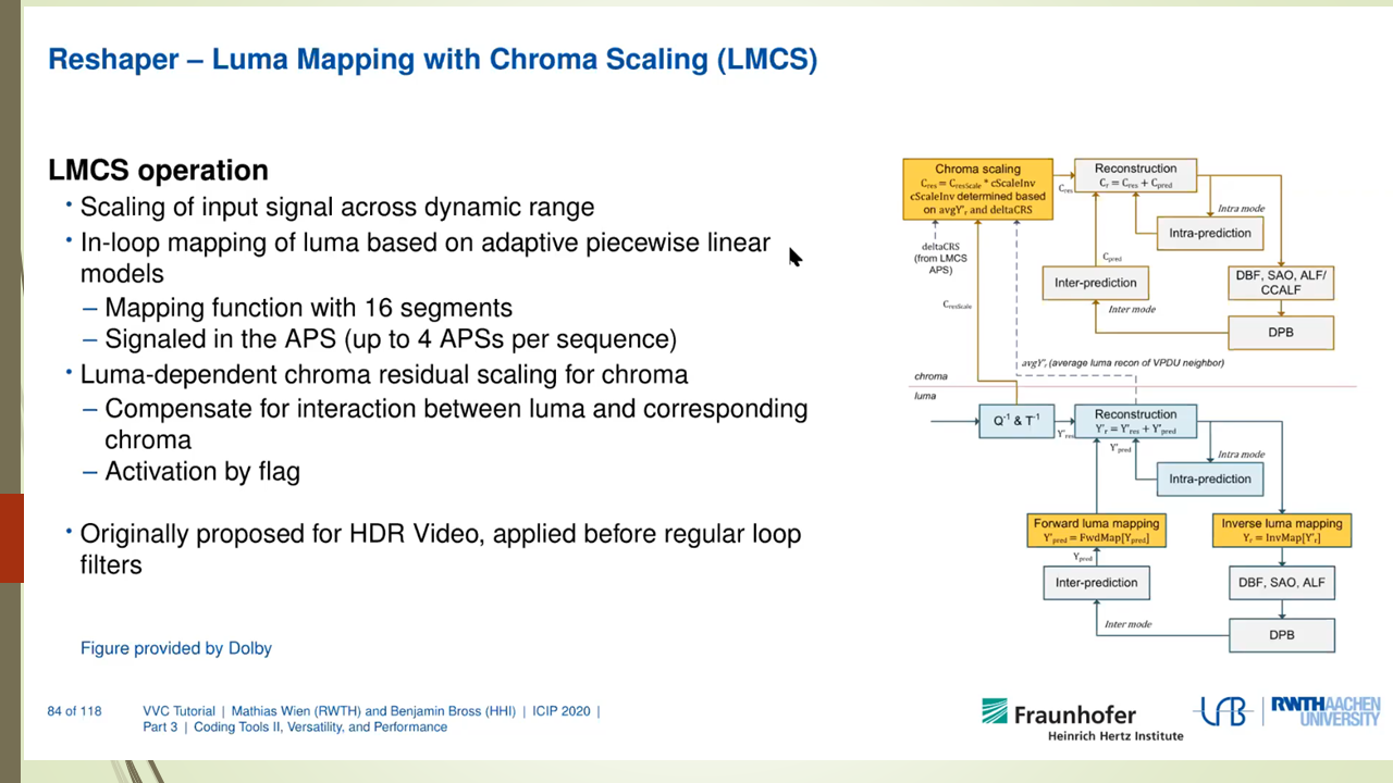
VVC是Versatile Video Coding的简写,也称为H.266,是下一代视频压缩标准,VVC已经于今年7月份完成标准的制定。VVC虽然没有突破传统的block based hybird的视频编码架构,但是借助于各种coding tools优化效果的累积效果,其编码效率比上一代视频压缩标准HEVC提升50%左右,也就是说VVC和HEVC达到相同的编码质量,VVC的码率能比HEVC节省50%。
对于VVC中的各种coding tools,笔者会在后续的文章中介绍。
本文介绍一下VVC标准中没有包含的一种coding tool,就是借助于Neural Network来优化视频压缩的方法。在VVC的多次会议的提案中都包括了借助于Neural Network来优化视频压缩的方法。至于这些提案最后没有进入标准,一个原因是这些方案的压缩效率提升不少很明显,而且适用范围有限。另外也可能和计算的复杂度有关,例如有些提案在CPU上的解码时间会增加好几倍。笔者觉得对于未来的视频标准(H.267?)来说,可能会采纳类似的方案,也许那个时候GPU解码会成为标配,为了追求极致的压缩效率,复杂度的增加也许会变得可以接受。
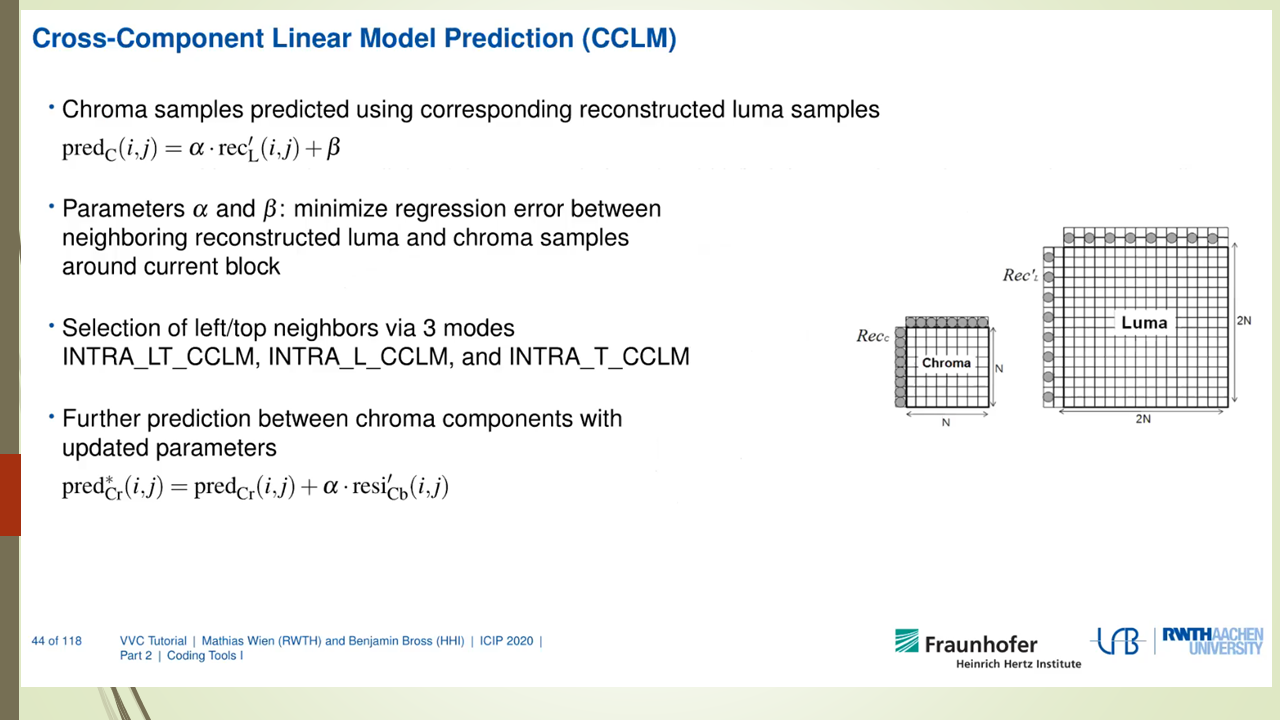
笔者分析了VVC提案中Neural Network的有关提案,发现基本集中在Loop Filter部分较多,这个和目前热门的Super Resolution技术解决的问题类似,也就是通过NN的方法把图像中失真的信息尽量还原回来,VVC中失真是指通过编码器量化过程以后,码流中包括的信息和源图像是有失真,而NN Filter可以很好的完整失真信息的还原。
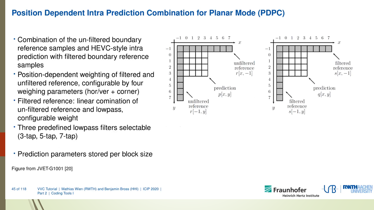
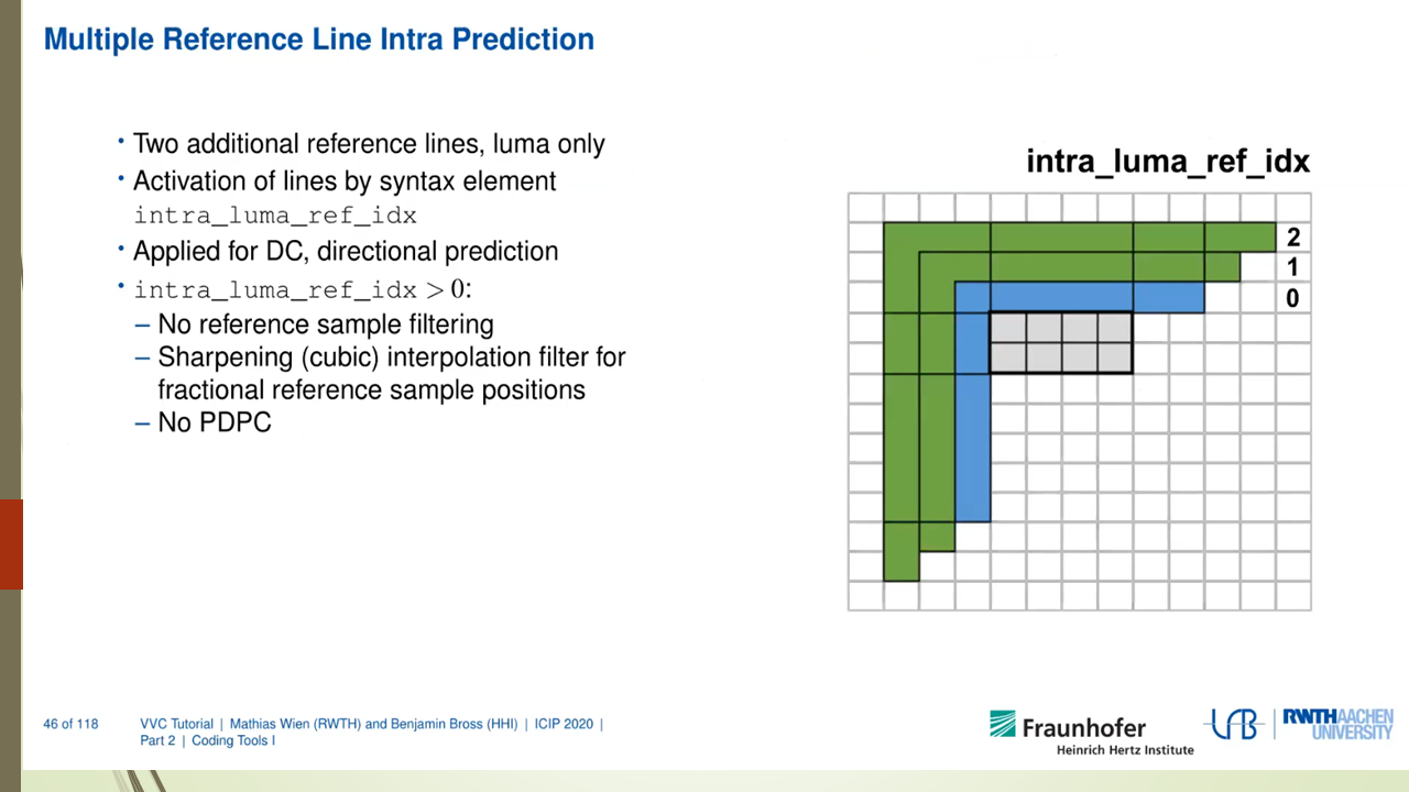
另外VVC的提案中也包括了采用Neural Network来优化Intra Prediction和Rate Control编码效率的方案。
下面对VVC中有关Neural Network的提案进行总结归类。
0x2 关于Neural Network based Loop Filter的提案
Neural Network based Loop Filter的提案又包括了下面这几种。
0x21 JVET-I0022 Convolution Neural Network Filter (CNNF) for Intra Frame
0x211 JVET-I0022 Convolution Neural Network Filter (CNNF) for Intra Frame (Hikvision)
VCC中包括了BF/DF/SAO filter这几个传统filter,这几个filter的作用是remove artifacts or improve coding performance。
CNNF用于替换这些传统filter。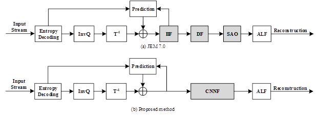
网络结构如下图所示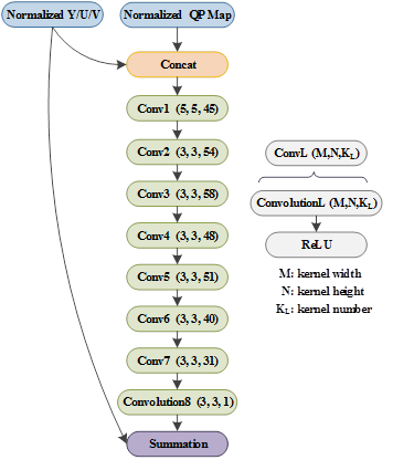
0x212 JVET-J0043 Convolutional Neural Network Filter for inter frame (Hikvision)
为了避免over-filter造成artifacts,采用RDO方法来选择是采用传统的Filter还是CNN filter。选择filter的flag通过CABAC编码。
0x213 JVET-N0169 Convolutional Neural Network Filter (CNNF) for Intra Frame (Hikvision)
对CNNF放置在deblocking的不同位置的编码性能进行比较。
Comparison of intra decoding scheme between different positions of CNN filter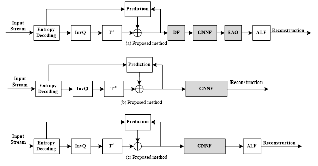
优化结论如下。
Driven by the advances of deep learning, a CNN-based filter for intra frame is proposed to remove the artifacts. Simulation results report -3.48%, -5.18%, -6.77% BD-rate savings for luma, and both chroma components for VTM-4.0 with AI configuration as the CNNF before the SAO. As the DF and SAO are turned off, the CNNF brings -4.65%, -6.73%, -7.92% BD-rate savings with ALF behind. Even though all the conventional filters are turned off, the CNNF still brings 4.14%, -5.49%, -6.70% BD-rate savings.
0x214 JVET-K0158 Separable Convolutional Neural Network Filter with Squeeze-and-Excitation block(Sharp)
对JVET-I0022进行进一步优化,减少CNN网络参数,可以达到和JVET-I0022类似的编码优化效果。
0x22 JVET-K0222 Convolution neural network loop filter (MediaTek)
设计了CNN Loop Filter,对reconstructed samples进行loop filter处理。
如下描述,这个CNN的parameter是在encoder的过程中通过online的方式生成的。 不像其他几种提案完全是通过offline的方式来生成。
only those pictures with temporal ID equal to 0 or 1 are used to derive CNNLF parameters in the training process. That is, only these pictures are required to be encoded twice. The first round is to generate the required data for CNNLF training process and derive the CNNLF parameters. The second round is to generate the final bitstream by enabling CNNLF with the derived parameters.
如下图所示,这个CNNLF添加在adaptive loop filter (ALF)的后面, CNNLF的输入是ALF输出的reconstructed samples。CNNLF的输出被称为 restored samples.

JVET-M0159, Convolutional neural network loop filter (MediaTek)
其对K0222进行了优化,主要是简化NN网络。JVET-M0159和JVET-K0222的差异如下。

0x23 JVET-K0391 Dense Residual Convolutional Neural Network based In-Loop Filter (Tencent, WHU)
在SAO前面加入dense residual convolutional network based in-loop filter (DRNLF)
In-loop filters, such as DF (deblocking filter), sample adaptive offset (SAO), are employed in VTM for suppressing compression artifacts, which contributes to coding performance improvement.
In this contribution, the proposed DRNLF is introduced as an additional filter before SAO
Proposed decoding scheme in VTM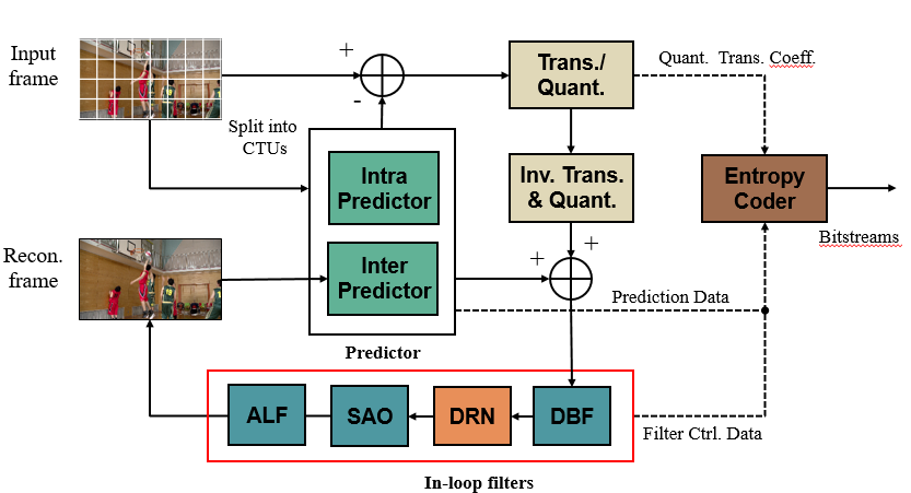
JVET-L0242 Dense Residual Convolutional Neural Network based In-Loop Filter(Tencent, WHU)
JVET-L0242对JVET-K0391进一步优化,减少了NN网络的参数。另外为了防止over-filter,采用如下图所示的RDO方法来决策是否采用DRN。
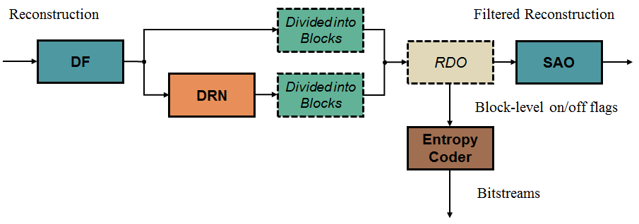
0x24 JVET-L383 Convolution Neural Network Filter(KDDI)
提案也是采用Convolution Neural Network Filter去替换目前的multiple filter such as deblocking filter (DBF), sample adaptive offset (SAO) and adaptive loop filter (ALF)。另外CNN Filter参数在encoder端和decoder端是相同的。
优化结论如下。
The simulation results show the BD-rate for luma is -0.93% for AI where CNNF is replaced by DBF, SAO and ALF though the BD-rate is -2.21% for AI where CNNF is replaced by DBF and SAO only.
The filter structure is shown in Figure 1. This filter has four layers with 3x3 taps. The input of sum block is residual signal from the left and reconstructed signal before all in-loop filters from the bottom. The output of sum block is filtered pixels. Actual output is weighted sum of after filtered and before filtered pixels based on the distance of edge.
提出的CNNF的结构图如下所示。
0x25 JVET-M0510 CNN-based In-Loop Filter proposed by USTC
这个提案中提出的CNN filter具有如下特点。
- Lightweight deep convolutional neural networks
- Locate between DF and SAO
- -0.96%, -0.32%, -0.45% BD-rate savings for Y, Cb, and Cr components compared with VTM3.0 under AI configuration
0x26 JVET-M0566 Adaptive convolutional neural network loop filter (Intel)
该提案提出了ACNNLF的设计,通过online training的方式得到3 CNN based loop filters。每个filter都是a small 2 layer CNN with total 692 parameters。在编码过程中为每个CTB的luma、chroma选择3个ACNNLFs之一作为loop filter。这三个ACNNLFs的网络参数会被写入到slice header中,然后每个CTB要选择哪个ACNNLF的话,只需要一个index指定到slice header的ACNNLFs的网络参数即可。
ACNNLF在解码流程中的位置如下图所示。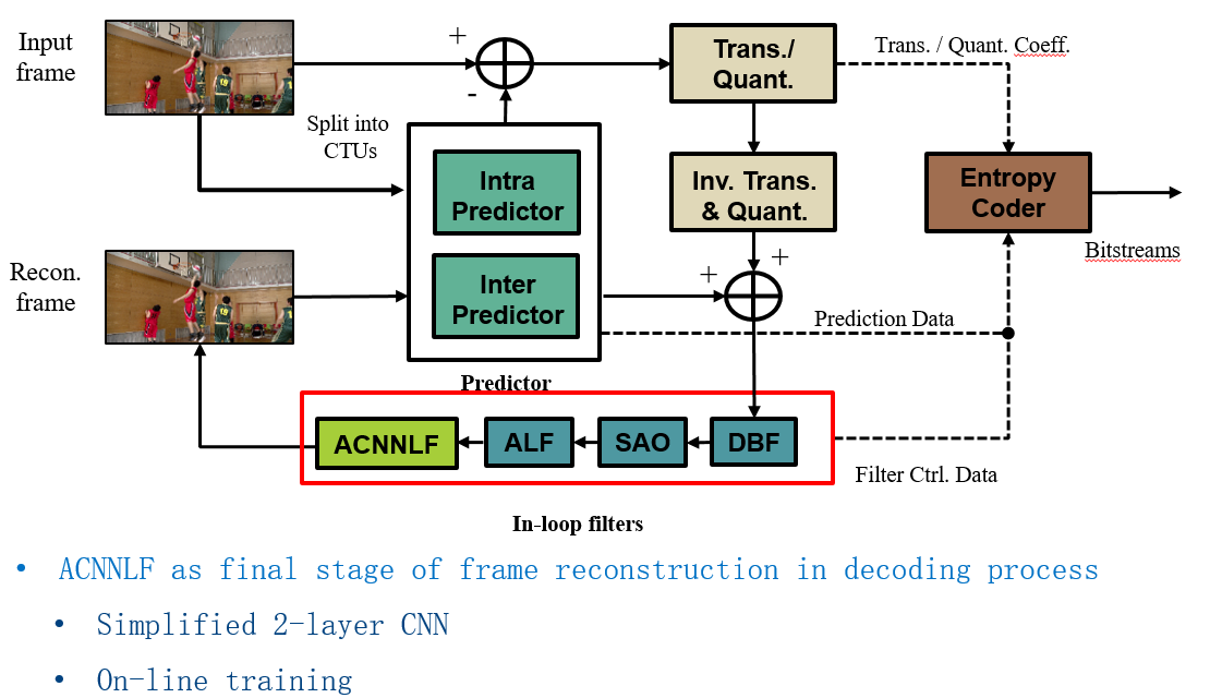
下面说明了ACNNLF的设计思想,主要体现了adaptive的online training的思想。
The ALF filter can be considered as a special one-layer CNN with linear activation. However, the number of filter coefficients in an ALF filter is too small to capture relevant features in the video. In order to match different video content, many ALF filters are used. Therefore, ALF makes up the deficiency of small number of filter coefficients by increasing the number of filter classes used.
As we try to further reduce the number of CNNLF parameters, we increase the number of CNNLFs to choose from to ensure the design can adapt to diverse video content without sacrificing performance. In this document, we propose an ACNNLF design:
- Small Deep-CNN loop filter with minimum number of hidden layers (2 CNN layers);
- 3 set of CNN loop filters trained online for luma and chroma respectively to better adapt to the content.
Since the number of ACNNLF filters (3) is small, it is possible to conduct exhaustive search for the optimal ACNNLF in the encoding process. The ACNNLF selection is indicated in the coded stream to the decoder. ACNNLF is applied after ALF in the decoding process.
采用了ACNNLF的优化结论如下。
This contribution presents an ACNNLF design with 3 classes of CNN based loop filters, where each filter has only 2 CNN layers and 692 parameters. The 3 ACNNLFs are adaptively trained with video sequence data. The best ACNNLF is selected for luma and chroma respectively for each CTB at encoder and indicated to decoder in coded stream with 2 bit indicator at CTB level. Compared with VTM-4.0-RA, the proposed ACNNLF achieves -1.14%, -0.21%, and -1.18% BD-rates for Y, U, and V, respectively, for Class A1 video sequences; -0.98%, -14.37%, and -16.96% BD-rates for Y, U, and V, respectively, for Class A2 video sequences; -0.55%, -21.79%, and -20.04% BD-rates for Y, U, and V, respectively, for Class B video sequences; and 0.09%, -2.75%, and -1.43% BD-rates for Y, U, and V, respectively, for Class C video sequences. The decoding time in the RA is 127% on VTM 4.0.
0x27 JVET-O0079 Integrated in-loop filter based on CNN (Tests 2.1, 2.2 and 2.3)
Northwestern Polytechnical University (NPU), Xidian University, Guangdong OPPO Mobile Telecommunications Corp., Ltd
提出采用WSE-CNNLF(Wide-activated Squeeze-and-Excitation Convolutional Neural Network Loop Filter)作为in loop filter,具有下面的特点。
- It includes six inputs: three reconstructed components (Y, U, V) and three auxiliary inputs (QPmap, CUmap for luma, CUmap for chroma).
- It consists of three stages to make the luma and chroma components jointly processed and separately fused with the corresponding CUmap before generating outputs.
- It can replace and even outperform the multiple filters in current VVC.
Main structure of the proposed CNNLF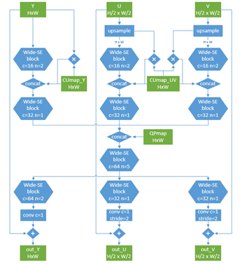
该提案的优化结论如下。
For test 2.1, it can be seen that converting weights from 32bit-float to 8bit-int leads to lower gains (from -0.46% to 0.79% for BD-rate saving on luma).
For test 2.2, in AI configuration, the BD-rate saving on luma of in-loop filter (-3.93%) is higher than that of post filter (-3.05%). In RA configuration, the BD-rate saving on luma of post filter (-1.89%) is higher than that of in-loop filter (-0.26%). It is noted that the proposed NN filter completely replaces the original in-loop filter (i.e., DBF+SAO+ALF ) when test 2.2a is performed to evaluate the in-loop situation, while it is added as a post filter with DBF+SAO+ALF all on in 2.2.b. It is concluded that the proposed NN filter reportedly outperforms DBF+SAO+ALF if used as the only in-loop filter, and is also useful if used as an extra post-loop filter.
For test 2.3, it’s shown that the proposed WSE-CNNLF has generalization capability on higher QP. The BD-rate saving is -0.46%, -4.11%, -2.80% when the test QP is the same as training QP, and -1.52%, -6.15%, -4.31% when the test QP equals to training QP+5. The CNN-based loop filter seems to be more effective on lower video qualities.
0x3 采用Neural Network来加速CTU partition加速和优化编码效率
JVET-J0034 CNN-based driving of block partitioning for intra slices encoding
该提案的算法描述如下。
for driving the encoder by estimating probabilities of blocks or Coding Units (CU) splitting in intra slices. The approach is primarily based on a texture analysis of the original blocks, and partly replaces the costly Rate Distortion Optimization (RDO) potentially involved for testing all potential partitioning configurations.
Overview of the split prediction process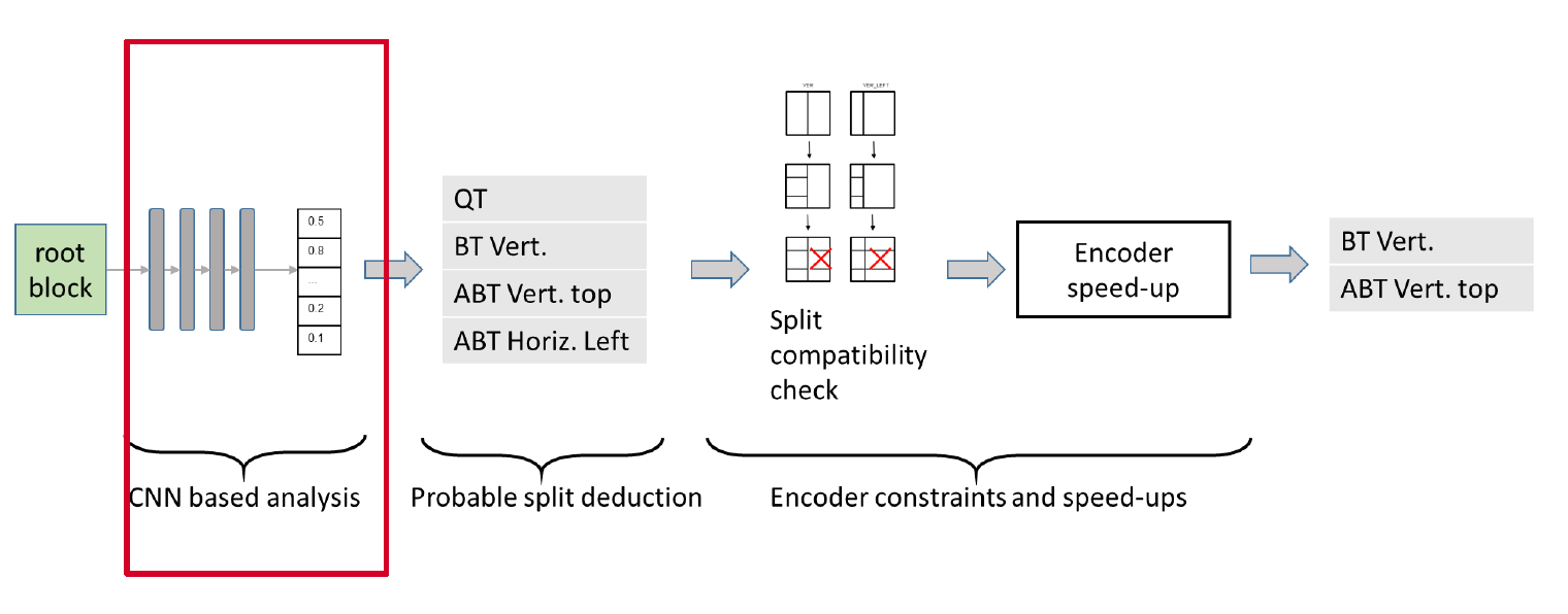
This module precedes the usual RDO process, and pre-selects the split configurations to be tested by the RDO. It is composed of the following 3 steps:
- CNN-based analysis – In the first step, each input 65×65 patch is analyzed by a CNN-based texture analyzer. The output of this step consists in a vector of probabilities associated to each one of the elementary boundaries that separate elementary sub-blocks. Figure 2 illustrates the mapping between elementary boundary locations and the vector of probabilities. The size of elementary blocks being 4×4, the vector contains n=480 probability values. The CNN is described in section 3.
- Probable split selection – The second step takes as input the probability of each elementary boundary and outputs a first set of splitting modes among all possible options, which are: no split, QT, BT (vertical, horizontal), ABT (top, bottom, left, right). This step is further detailed in section 4.1.
- Encoder constraints and speed-ups – The third step selects the final set of splitting modes to be checked by classical RDO, depending on the first set provided by step 2, the contextual split constraints described in JVET-J0022 section 3.1.1.3 and the encoder speed-ups described in JVET-J0022, section 3.1.2.1. This step is further detailed in section 4.2.
该提案的优化结论如下。
在AI configuration情况下,在相关的编码时间情况下,比基准(JEM7)取得6%的BD-rate gain,在相同的BD-rate gain情况下,编码时间可以减少4.3倍。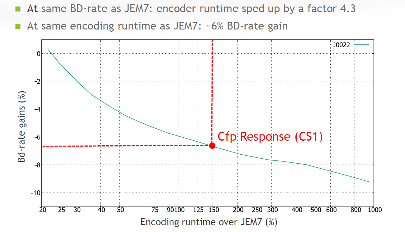
0x4 采用Neural Network来优化Intra Prediction
JVET-J0037 Intra prediction modes based on neural networks
如下图所示,通过NN的方法来得当前Intra block的预测像素值。
Prediction of MxN intra block from reconstructed samples using a neural network
如下图所示,通过NN的方法来得当前Intra block的预测mode值。
Prediction of mode probabilities from reconstructed samples using a neural network
0x5 采用Neural Network来优化Rate Control
JVET-M0215 CNN-based lambda-domain rate control for intra frames
This contribution proposes a CNN-based λ-domain rate control approach for intra frame coding. Compared with the exiting SATD-based intra rate control approach in VTM, we reuse the R-lambda model in VTM inter frame rate control and train one convolutional neural network to simultaneously predict the two model parameters, alpha and beta. Compared with the rate control method in VTM 3.0, the proposed method can achieve an average bd-rate reduction of 1.8% under All Intra configuration. When considering the mismatch between target bitrate and actually coded bit rate, the CNN-based method can achieve a smaller rate control error, especially for the first I frame.
通过下面的NN网络训练得到两个参数,这两个参数作为Rate Control的后续输入参数。
We propose to reuse the model and train one convolutional neural networks to simultaneously predict the two parameters. The network architecture is depicted in Fig.1. Specifically, before the encoding for one Intra frame, we extract the luma component, as well as the chroma components of each CTU and feed them into the two trained CNN, from the CNN output we can obtain the corresponding and for each CTU.
CNN-based rate control的网络结构图如下所示,从图中可以看到是用一个网络来预测两个参数。

0x6 有关Neural Network的参数传递
JVET-N0065 Comments on carriage of coding tool parameters in Adaptation Parameter Set
采用Adaptation Parameter Set (APS)用于动态传输neural network的参数。
In 13th JVET meeting, Adaptation Parameter Set (APS) has been introduced into Versatile Video Coding (VVC) standard text. A few years ago, the APS was once adopted into High Efficiency Video Coding (HEVC) standard for carrying coding tool parameters, such as Adaptive Loop Filter (ALF) parameters; but the APS was removed from HEVC standard along with the removal of ALF as a coding tool at a final HEVC standardisation stage. The APS was designed to carry coding tool parameters as a picture level adaptive nature and alternatively the APS data can also be maintained as unchanged for the whole video sequence for avoiding resending them unnecessarily. This contribution is for information only and it is commented and recommended to use the APS to carry the coding tool data, such as neural networks parameters and affine linear weighted intra prediction parameters, etc., if some associated coding tools are indeed to be adopted into VVC standard. If more coding tool data need to be carried by APS in the future, it commented that further study on updating parameters of multiple tools using APS would be needed.
It is recommended that APS can be considered as the carrier for coding tool parameters, such as neural networks coding parameters, etc., to convey these parameters in bitstreams to a VVC decoder. When more types of coding tool parameters are needed to be carried by APS, updating parameters of multiple tools using APS would need to be further studied for achieving more efficient use of the APS.
Intel vulkan driver introduction
0x1 Overview
As we know, mesa has supported vulkan driver for four different platforms, these four platforms are Intel,AMD,Qualcomm Adreno,Broadcom V3D. Currently vulkan driver support in mesa is not using Gallium architecture like OpenGL,its architecture seems child stage, the four vulkan drivers don’t have much shared common codes, the abstraction of the four vulkan drivers is the architecture optimization of mesa vulkan driver in the next stage.It has widely discussed in the mesa dev community.And the coming optimized architecture will accelerate the supporting for more GPU platforms like Mali GPU and Imagination GPU.
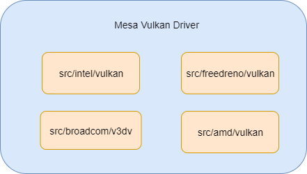
In this article, I will show you how Intel Vulkan driver is supported in mesa.
Let’s have a look of Intel GEN GPU hardware architecture.
The following diagram is about the hardware block of the Intel GEN GPU
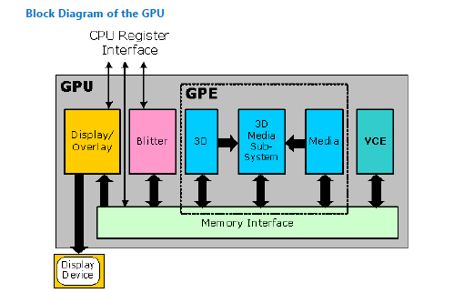

Here is the 3D pipeline block of Intel Gen GPU. the left part is the 3D pipleine, the right part is the GPU hardware block.
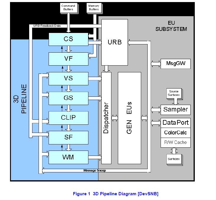
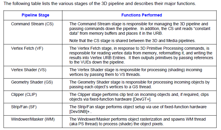
The GPU driver (userspace and kernel space) will configure the above hardware block according to graphics API’s input, then trigger gpu hardware to execute as its configuration. So GPU driver’s task is simple, just to configure the GPU hardware!
0x2 Component overview
We know mesa includes several abstraction layers. it supports different graphics api,different compiler frontend, different gpu hardware code generation.
In mesa, Intel vulkan driver’s module name is ANV.Here is the diagram about how ANV driver is built from different sub component.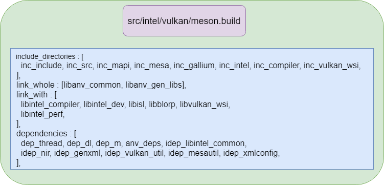
And here is the relationship of intel vulkan driver library and its dpendencies.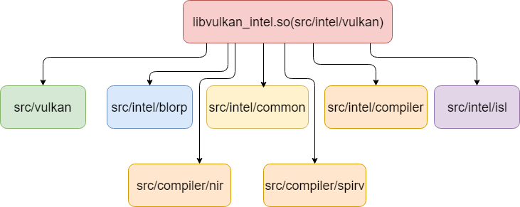
0x3 Mem interface
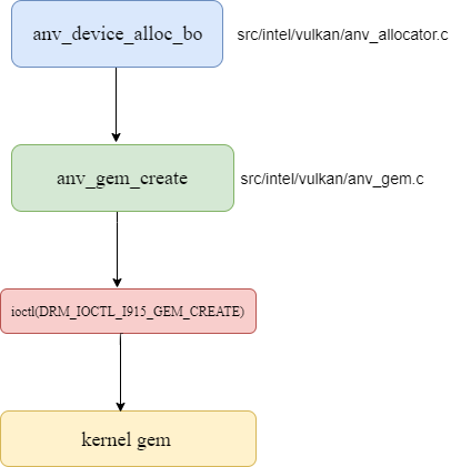
GPU harware needs serveral input data for further processing, like vertex buffer, texture buffer, uniform buffer and surface, these buffer will be accessed by CPU and GPU together. so mesa should provide interface to alloc/release buffer, set these buffer’s address to GPU hardware then issue hardware to execute it.
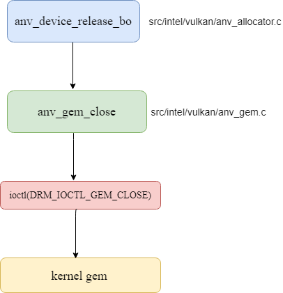
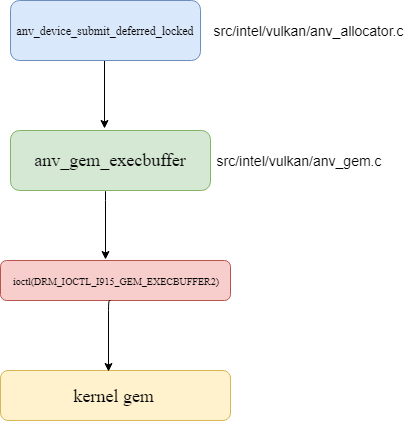
Let’s have brief explanation about how buffer alloc/release happen in ANV vulkan driver.
Here is the sequence about allocating gem buffer.
Here is the sequence about releasing buffer.
Here is the sequence about issuing command to kernel driver.
For performance optimization, ANV can use a cache mechansim to boost the performance since the memory alloc/release is resource heavy operation. In broadcom close source v3d driver, it uses a similar mechansim like linux slab to cache buffer in userland driver.
0x4 Typical objects in vulkan
Here are several important objects of vulkan concepts. RenderPass object and ShaderModule object are passed to Pipeline through VkGraphicsPipelineCreateInfo when creating Pipeline object. then Pipeline is binded to CommandBuffer using VkCmdBindPipeline api, after that the commanbuffer can use the passing Pipeline object, RenderPass object and ShaderModule object.
0x5 GPU codegen
Here is the diagram about generating gpu code from SPIRV code.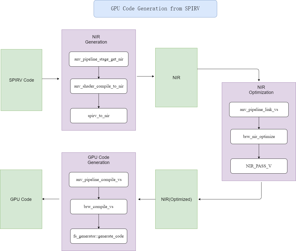
The gpu code is the code which will run on Intel GPU’s EUs(execution unit), it is programmable shader unit, likes broadcom v3d’s QPU.
The input of the pipeline is SPIRV code, the SPIRV format is the standard IR for different shader formats like glsl,opencl.
Then ANV driver will convert it to mesa internal IR format(NIR) code.
Then it will be optimized by different passes, this idea is similar as other compiler’s optimization passes.
The last step is gpu code generation.It uses typical graphic coloring algorithm. at this stage,we must read the GPU programmer guide carefully,then learn how to generate effective code for intel gen gpu.
0x6 Framebuffer dump
This feature is useful for us to check the render result in the framebuffer. it is similar as we can use glReadPixels to read back framebuffer’s content on OpenGL.
Currently mesa’s anv dump code has bug to blit framebuffer to write image, and I have fixed it to make this feature can work well.
Here is the diagram about how to dump framebuffer.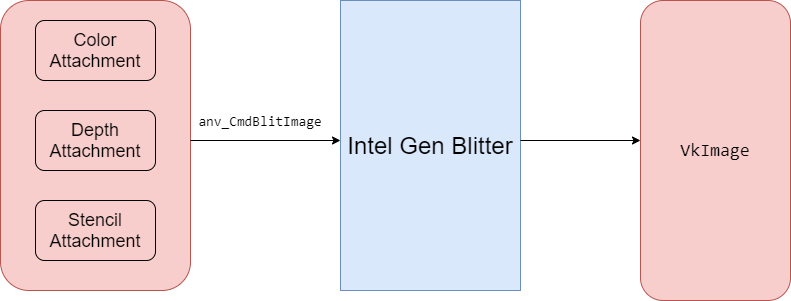
It uses gdb call method to dump data, here is the use instruction about it.
- To dump the framebuffers of an application after each render pass, all you
- have to do is the following
* - 1) Start the application in GDB
- 2) Run until you get to the point where the rendering errors occur
- 3) Pause in GDB and set a breakpoint in anv_QueuePresentKHR
- 4) Continue until it reaches anv_QueuePresentKHR
- 5) Call anv_dump_start(queue->device, ANV_DUMP_FRAMEBUFFERS_BIT)
- 6) Continue until the next anv_QueuePresentKHR call
- 7) Call anv_dump_finish() to complete the dump and write files
Here is the dump result with the above method.
0x7 Hardware state dump
It uses preload method to hook api, the hook api will dump state to a file.
Here is the diagram about it.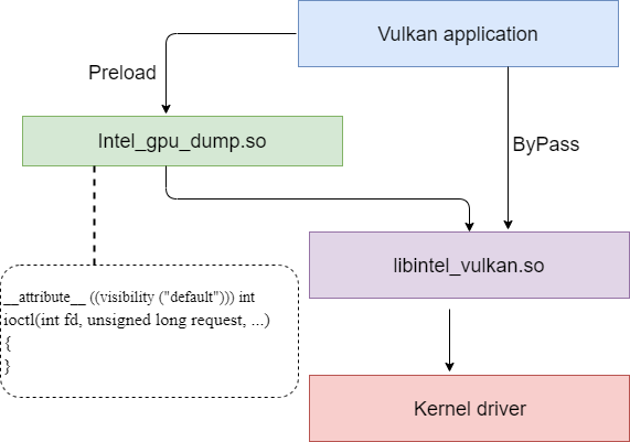
Here is the gdb command for capturing data
gdb -iex “set exec-wrapper env LD_PRELOAD=/home/kevin/mesa/mesa_build_vulkan/libexec/libintel_dump_gpu.so INTEL_DUMP_GPU_CONFIG=/home/kevin/mesa/test_intel_dump_gpu/dump_config” –args “/home/kevin/vulkan/build/bin/multithreading”
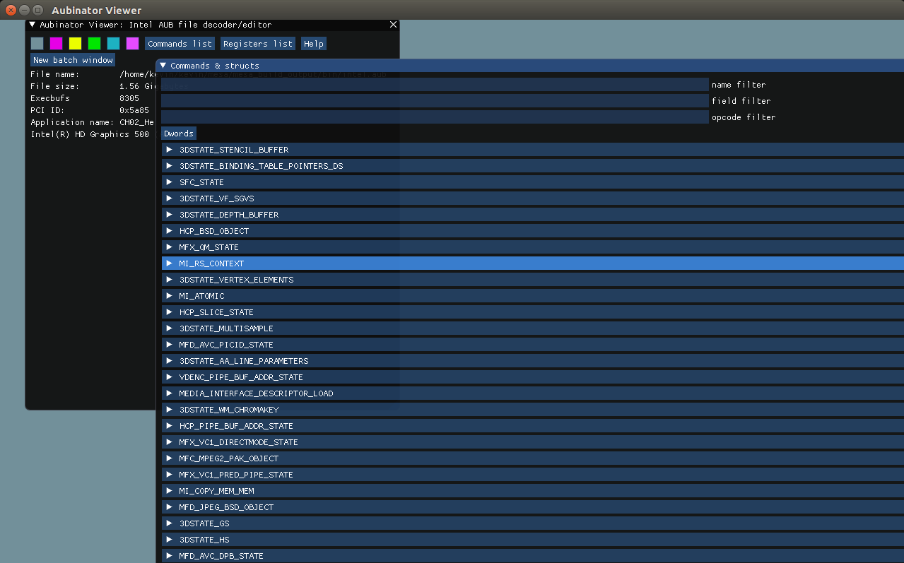
Then we can use Aubinator Viewer to check the dumped states. please notice that this dump mechansim is also working for Opengl case, and the dump items are the same as Vulkan’s since the dump is for getting content of gpu hardware statue.
The dump item shows what vulkan driver program the hardware. we can see the following states’s content like 3DSTATE_VS and other states.
EGL in Mesa
0x1 EGL介绍
我们知道通过OpenGL来绘制的时候需要和EGL配合才能完成渲染,本文主要来介绍一下mesa中的EGL驱动实现。下面先来简单介绍一下EGL。
EGL用于管理绘图表面,其主要提供了下列几种功能,
a 与设备平台的原生窗口系统进行交互。
b 查询可用的绘制类似和相关配置。
c 创建和管理绘制surface。
d 创建和管理绘制context。
e 提供present接口eglSwapBuffers,一般通过交换前后缓存区来实现。
EGL驱动中包括了对下面这些EGL API的封装,应用调用这些API来和EGL驱动交互。
mesa中egl架构如下图所示。
对上图简单说明如下,
从上图左上角可以看到,EGL需要和具体显示平台的窗口NativeWindow交互。这个NativeWindow需要在应用侧创建好,创建的NativeWindow是根据具体的平台(如Android, X11, Wayland)的不同而不同。这个应用创建好的NativeWindow通过调用eglCreateWindowSurface()传入到egl驱动中。
EGL还需要和绘制缓冲区对象(framebuffer)进行交互,这些缓冲区一般由EGL驱动调用外部窗口系统的提供的接口(如android上的surface)来分配和释放。绘制之前需要先得到空闲的buffer,绘制完成以后需要把buffer送给下一级pipeline,交出控制权。这里面一般会创建2~3个buffer,和下一级pipeline一起循环使用。这些buffer在pipeline的不同阶段流动,控制权也在各个阶段中流转,所以需要一种同步机制来保证buffer何时可读,何时可写,在android上是通过fence机制来保证的。
GL Driver调用EGL的内部接口(getBuffers)来得到当前绘制的目标buffer,然后GL Driver就可以发送绘制命令给GPU硬件,GPU硬件把渲染结果绘制到目标buffer中。
笔者的测试平台是Intel i3,GPU是Gen5xx,通过配置mesa的编译参数,可以编译出GPU平台相关的库是iris_dri.so。
这种配置下mesa中代码调用关系如下图所示。
从下图可以看出,mesa把驱动进行了分层,上面是通用的实现,对具体gpu平台相关实现都封装在xxx_dri.so中,这里Gen5xx平台对应的是iris_dri.so,对broadcom vc4 gpu来说,对应的是vc4_dri.so。
0x2 mesa中egl流程介绍
下图说明了一个OpenGL ES应用程序调用EGL接口来绘制的基本流程。
下面对流程中的egl api调用做详细的说明,
0x21 创建X11平台对应的Display和Window
首先在应用程序中通过下面的代码来创建x11平台上的display和window。
0x21 调用eglInitialize
该函数的调用堆栈如下。
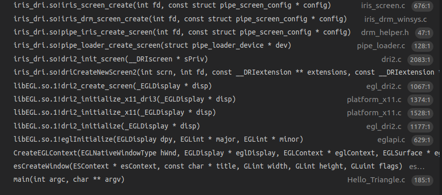
eglInitialize的参数是display,这就是前面调用
平台相关接口得到的x_display。
上面调用堆栈最后调用的函数是iris_screen_create,这是mesa的gallium架构下初始化具体gpu型号的硬件驱动的入口函数。
这个在后续的文章中会做详细的介绍,这里我们知道了应用调用eglInitialize()的时候会去调用具体的gpu型号的硬件驱动。
|
|
下图的调用堆栈说明了eglInitialize调用过程中的gem buffer分配操作。这个操作最后会调用到kernel 驱动中完成内存分配动作。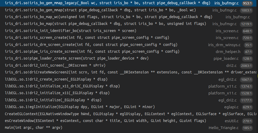
0x22 eglCreateContext的调用流程
eglCreateContext的调用堆栈如下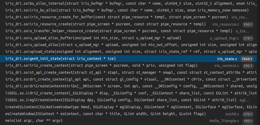
EGL驱动最后会调用到iris driver中创建context的代码中,其中包括了初始化各种函数指针的代码,包括program, clear, blit等操作。
|
|
下面是iris创建context的时候初始化state相关函数指针的代码。
0x23 和外部NativeWindow的交互
主要是buffer的管理, 通过dequeueBuffer取得空闲buffer供本次绘制使用,在绘制完成了以后,再调用queueBuffer把buffer送去显示。另外外部NativeWindow大小发生变化的时候,也需要调用相应的接口来通知mesa,这个时候一般的流程是先把前面分配的旧的大小的buffer释放掉,然后重新去分配新的大小的buffer,另外还需要调用glViewPort重新设置draw区域的viewport大小。
0x24 gl driver如何取得当前绘制的buffer
GL Driver调用EGL的内部接口(getBuffers)来得到当前绘制的目标buffer。
下图是eglMakeCurrent函数执行的时候分配绘制buffer的堆栈。
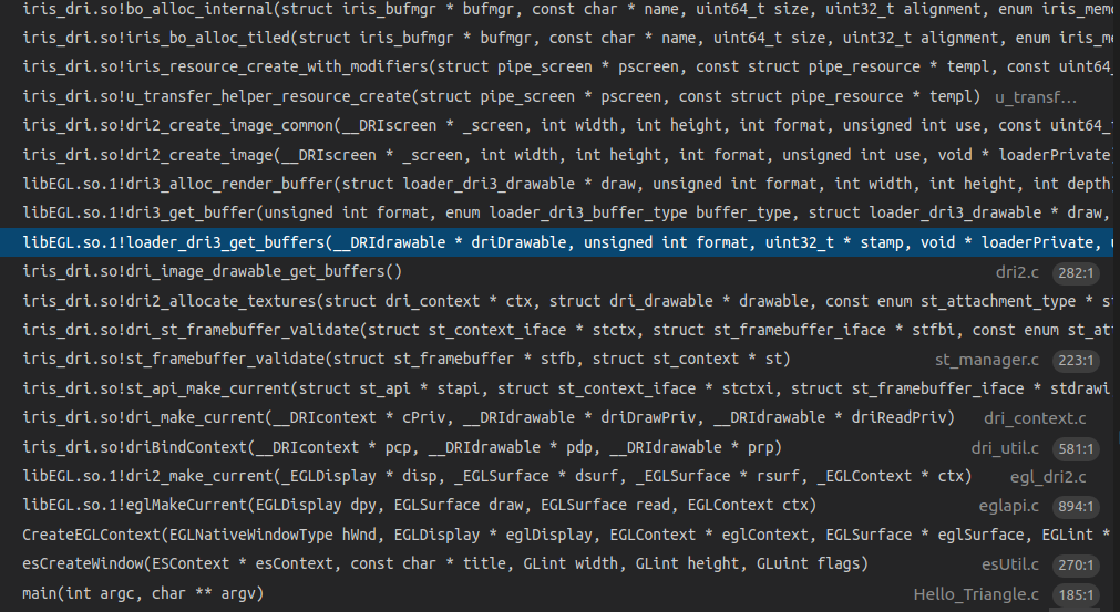
具体的调用代码如下所示,外部通过getBuffers来调用具体egl driver的buffer接口。对x11_dr3而言,最后调用的函数是loader_dri3_get_buffers,在这个时候会返回需要的buffer,如果有必要也会重新分配buffer。
|
|
0x25 glClear
glClear的调用堆栈如下,可以看到这个时候也需要分配buffer。
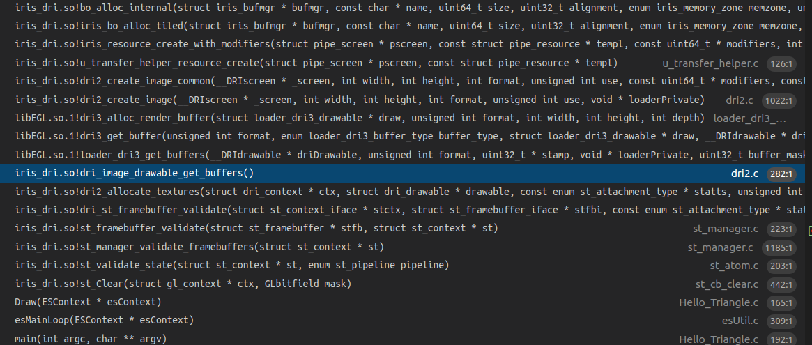
0x26 eglswapbuffer流程
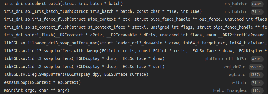
通过调用相关的OpenGL ES API,把需要的绘制资源,如顶点数据(VBO/VAO等),纹理资源(glTexImage2D)等准备好,mesa内部也构造好了对应GPU需要执行的command,这个时候可以启动GPU来绘制了。在函数submit_batch中通过调用DRM_IOCTL_I915_GEM_EXECBUFFER2 ioctl命令来启动kernel的绘制动作。
0x27 egl驱动中实现的其他功能,如chooseConfig
这部分主要是软件逻辑,根据硬件平台的能力,对configure进行管理。
About SceneGraph
0x1 什么是SceneGraph
渲染引擎需要解决的问题是如何把需要绘制的各种对象高效地组织起来并绘制出来,这其中很重要的概念是SceneGraph。目前各种渲染引擎包括2D UI引擎到3D引擎都实现了类似的概念。
其实SceneGraph应该称为SceneTree更合适,因为其中的数据组织一般是采用Tree的形式。
qt中采用的SceneGraph介绍如下
https://doc.qt.io/qt-5/qtquick-visualcanvas-scenegraph.html
cocos2d也有类似的概念如下
https://docs.cocos2d-x.org/cocos2d-x/v4/en/basic_concepts/scene.html
ogre中对SceneGraph的介绍如下
https://ogrecave.github.io/ogre/api/latest/_the-_core-_objects.html
0x2 SceneGraph包括哪些功能
典型的SceneGraph包括了SceneManager,RenderManager,ResourceManager, Camera, RenderTarget,Animation, Particle子模块,下面来简单介绍一下这些概念。
SceneManager提供对场景图的组织和管理,具体可以采用二叉分割树,八叉树等。
RenderManager提供了绘制相关操作,也就是通常所说的各种Backend,如OpenGL,Directx,Metal,Vulkan等。
ResourceManager提供了对资源的管理,包括Material, Mesh等。
Camera提供了在SceneGraph中模拟眼睛的功能。
Viewer是在SceneGraph遨游时的眼睛,通过变化Camera的位置,我们可以看到SceneGraph中不同的风景。其中提供lookAt()类似的函数来指定场景中眼睛的位置。
0x3 SceneGraph的设计
0x31 数据结构设计
渲染引擎一般采用场景节点和场景内容分离的机制,也就是说场景内容作为场景节点的成员变量,而不是把场景内容作为场景节点的子类。场景节点一般包含了类似位置,旋转等信息,场景内容指需要绘制的Mesh和渲染属性等。
另外一种实现方式是把场景内容作为场景节点的子类,这种实现方式把场景内容和场景节点耦合在一起,不利于添加新的场景内容的支持。
场景节点和场景内容分离机制带来了SceneGraph中数据松耦合的好处,场景内容添加到一个场景节点中,也可以从一个场景节点中移除。SceneManager控制的是场景节点,不需要关心具体的场景内容。我们可以精心设计场景节点的接口,这样可以保持SceneManager对场景节点的灵活控制。
下面是典型的SceneGraph数据结构图。
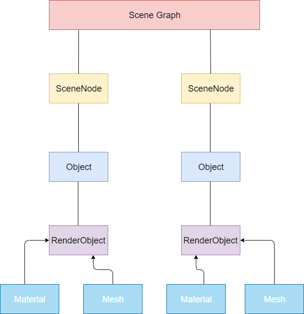
SceneNode表示场景节点。
Object表示场景内容。一个Object可以包括多个RenderObject,如房间可以表示为一个Object,房间里的一张桌子是RenderObject。
RenderObject表示可被渲染的内容。RenderObject需要通过Mesh和Material来绘制。如前所述,一张桌子是RenderObject,然后我们需要知道桌子的Mesh,需要知道如何设置Mesh的渲染属性如shader,color等。
0x32 场景图管理器
场景图管理器实现的功能有,
第一类是数据对象管理相关的功能,包括如下功能。
创建/删除SceneNode。
创建/删除Camera。
创建/删除各种Light。
创建/删除Object,前面提到Object作为场景内容节点挂接到SceneNode上。
创建删除各种绘制对象,设置各种绘制属性。
创建/删除ParticleSystem。
创建/删除AnimationSystem。
另外是渲染流程相关功能,包括如下,
查找当前Camera可见的渲染Object。
渲染前面查找到的渲染Object
场景图管理器的结构图如下所示,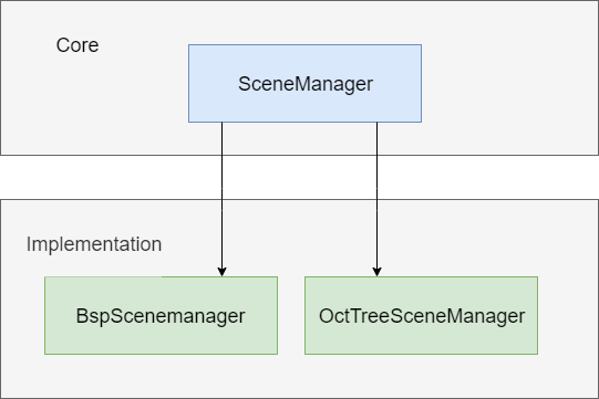
Core下面的SceneManager提供了基本的框架和系统中其他模块交互,对应于具体的SceneManager而言,如上图所示的BspScenemanager和OctTreeSceneManager,其核心功能是解决如何高效地查找到当前Camera可见范围内的渲染Object,因为场景图中包括了很多数据,如在关卡游戏中,场景图中包括了很多游戏关卡,如果都去渲染,性能可能很差,所以通过SceneManager快速找到Camera可见范围内的渲染Object,然后只需要渲染这些Object。
0x33 渲染管理器
渲染管理器的结构图如下所示,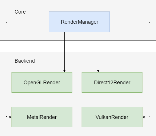
渲染管理器也称为渲染的后端,这里来谈一下如何设计渲染管理器的接口使特定后端的代码量最少。也就是说如何把功能尽量放在Core中,Backend只保留特定平台相关的实现,这部分也是比较各种渲染引擎的跨平台技术做的好坏的评价标准之一。
RenderManager需要抽象出下面的模块作为通用的接口,这些是所有Backend都具备的特性,是公共的模块。在具体的Backend模块中中去继承这些接口从而实现各个Backend的对接。
Texture操作接口。
HardwareBuffer操作接口,包括Index bufer/Vertex buffer/Uniform buffer/Texture buffer等。
Shader/Program操作接口。
DrawCall操作接口。
0x4 渲染流程设计及优化
0x41 数据准备
绘制内容的设置
绘制内容包括各种资源,如Mesh,Skelton,Shader等。他们通过各种ReaourceManager加载进来。
绘制坐标的设置
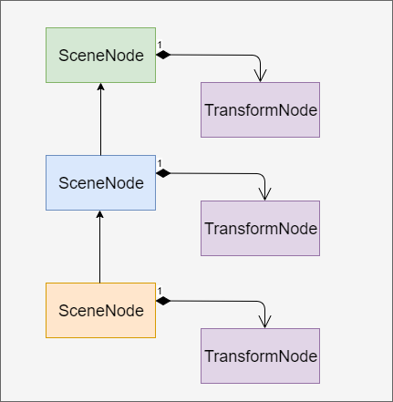
如果SceneNode存在父子关系,有两种方法来设置绘制坐标,第一种是在生成绘制内容的时候,根据父节点的坐标计算好当前节点的坐标,然后设置到SceneNode中。另外一种方法是给SceneNode设置一个TransformNode作为SceneNode的成员,这个TransformNode是计算好的本地坐标系坐标(没有考虑父子关系),这样在包括所有SceneNode的tree创建好了以后,再去从根节点开始遍历这颗树,根据父子关系,计算出每个SceneNode的世界坐标。具体实现中推荐采用第一种方法,因为如果SceneNode的层次太深,递归遍历节点的时候可能会出现栈溢出。
具有父子关系的SceneNode结构图如下所示。
0x42 数据绘制
场景绘制的完整流程如下,
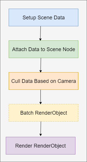
首先是设置好场景数据,这些场景数据可以是通过离线工具如Blender,由美工来制作完成并导出,然后再加载进来。渲染引擎也可以提供在线实时生成场景数据的功能,如生成矩形,球形,立方体等。设置好的场景数据封装成RenderObject,再由RenderObject组成Object。
然后是需要把场景数据挂接到场景图的SceneNode中,这样场景图管理器就拥有了场景数据了,可以根据视点在场景图中执行查询等操作。
然后开始根据Camera的位置找到可见范围内的RenderObject,这个也就是前面提到的SceneManager发挥作用的地方,可以简单地称为Culling操作。
找到了需要渲染的RenderObject集合,可以对这些RenderObject的渲染顺序进行Bactch优化,如果两个RenderObject需要的渲染Maerial是一样地,可以合并成一个drawcall,这种优化方式我们称为动态Batch。如果由美工在素材制作阶段对场景数据的组织进行优化,把能用一个drawcall进行渲染的物体合并起来,这种优化被称为静态Batch。
优化好了以后就开始调用具体的Backend进行渲染了。
0x43 流程优化
如下图所示,可以把渲染过程划分成两个线程并行处理,这样在数据加载阶段可以做上一帧的绘制动作,等数据加载完成再同步给渲染线程。

另外一个优化是资源的异步加载,如果前面的Load Thread同时要响应用户操作,如果长时间在运行,会造成UI卡死,这个时候可以通过开启异步线程来处理。
0x5 SceneGraph的发展方向思考
SceneGraph技术作为各种渲染引擎的根基,目前是很完善的技术了。包括光线跟踪渲染引擎,其中也包含了SceneGraph的实现。如果要考虑未来方向,是否可以和其他方向结合,如人工智能等?搞出一套智能的渲染引擎。如是否可以用CNN来加速特大场景图的可见渲染物体查询?